DMM Soft Front Panel
You can use the DMM Soft Front Panel (DMM SFP) to take measurements and to test the functionality of the National Instruments DMMs. To launch the DMM SFP, navigate to Start»All Programs»National Instruments»NI-DMM»NI-DMM Soft Front Panel.
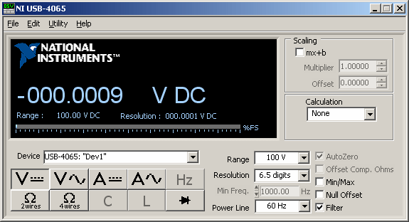
When using the DMM SFP, you have the option of making the following selections, based upon the measurement mode and functionality that your application requires:
- Select the DMM that you want to use.
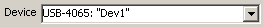

Tip If you cannot select the DMM you want to use, make sure it is available in Measurement & Automation Explorer (MAX). - Select a measurement function.

DC Voltage 
AC Voltage 
DC Current 
AC Current 
Frequency
(NI 4070/4071/4072 only)
2-Wire Resistance 
4-Wire Resistance
(NI 4050 not supported)
Capacitance
(NI 4072 only)
Inductance
(NI 4072 only)
Diode - Select the range.


Available ranges depend upon the DMM and the selected function that you are using. The range box displays a list of available ranges for each function and device. For most functions, you can also select Auto Range and let the device select a range for you. When you select Auto Range, resolution is also automatically selected and shown on the display. The input signal in relation to the selected range is represented on the display as a percentage of full scale.
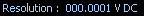
Note If the front panel displays OVLD, an overrange condition has occurred. If the front panel displays UNDRNG, an underrange condition has occurred. - Select the resolution.
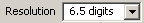
The maximum resolution depends upon the device that you are using.
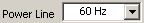
The display shows the resolution in absolute units. Refer to Resolution for more information.Note The NI 4065 and NI 4070/4072 have an available 6½-digit resolution. The NI 4071 only has an available 7½-digit resolution for the resistance and DCV modes and an available 6½-digit resolution for all other measurement modes. - Select the powerline frequency that you want to reject. The NI 4060 and NI 4050 use this value to select an aperture time to reject powerline noise by selecting the appropriate internal sample clock and filter. The NI 4065 and NI 4070/4071/4072 use this value to select a timebase for setting the Aperture Time property in Powerline Cycles (PLCs).
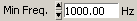
- For AC and frequency measurements, set the minimum expected frequency of the input signal.
- Enable Auto Zero.

Auto Zero allows the DMM to compensate for any offsets in the measurement path or ADC. When Auto Zero is enabled, the internal DMM input HI is connected to its input LO and measured. The subsequent input signal is measured, and the Auto Zero value subtracted from it.Notes The NI 4050 does not support Auto Zero.
For the NI 4065, Auto Zero is always ON. Auto Zero is an integral part of the signal measurement phase and adds no extra time to the overall measurement. - Enable Offset Compensated Ohms (NI 4070/4071/4072 only).

Offset Compensated Ohms allows the DMM to eliminate voltage offsets in resistance measurements. When Offset Compensated Ohms is enabled, the DMM makes two resistance measurements (one with the current source n and the other with it turned off), and the second measurement is deducted from the first measurement. Any voltage offset present in both measurements is cancelled out. Offset Compensated Ohms is useful when measuring resistance values of less than 100 Ω. - Perform cable compensation (NI 4072 only).
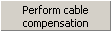


OPEN/SHORT Compensation allows you to minimize the errors between the NI 4072 and the DUT. You can choose to perform OPEN, SHORT, or both OPEN and SHORT cable compensation. Compensation consists of measuring the error and applying the measured error to the actual measurement to correct and minimize the errors introduced by the test system. The compensation functions must be set before taking any measurement at a specified function and range. Therefore, with any change in range or function, you must perform cable compensation again. - Configure the display.


Min/Max displays the maximum and minimum values during the acquisition and is shown on the display. When enabled, the Min/Max display is reset to the latest value if the device, function, or range is changed.


Null Offset stores the current reading of the DMM and subtracts it from any future readings. The stored offset is shown on the display. When enabled, the Null Offset value is updated if the device, function, or range is changed.

Filter allows the DMM SFP to display a running average of the measurements acquired. For AC measurements, eight readings are averaged. For DC measurements, four readings are averaged. - Apply a calculation.
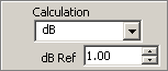
dB allows the input voltage to be compared to a reference voltage you select on a logarithmic scale and expressed in decibels. dB is defined in the following equation:
dB = 20 log(Vin/ Ref)
where Vin is the DC or AC signal and Ref is the specified voltage reference level (db Ref).
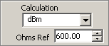
dBm is defined as decibels above or below a 1 mW reference. With a user-defined reference impedance (Ohms ref), DMM SFP reads 0 dBm when the voltage needed to dissipate 1 mW through the reference impedance is applied. The relationship between dBm, a reference impedance, and the voltage is defined by the following equation:
dBm = 10 log((Vin2)/(Ohms ref))/1 mW
where Vin is the DC or AC input signal.
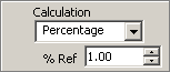
Percentage applies a percentage calculation. The displayed reading is expressed as a percent deviation from the reference value. The percentage calculation is performed as follows:
Percent = (Input—Ref)/(Ref) x 100
where Input is the normal display reading and Ref is the constant you select (% Ref). - Apply Scaling. If a calculation or Null Offset is selected, these are applied before the measurement is scaled.
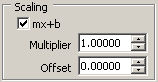
Multiplier (m) multiplies the reading by the number you select. For example, a 7 V reading with a scaling multiplier of 2 would read 14 V.
Offset (b) adds the number you enter to the reading. For example, a 7 V reading with an offset of 0.5 would read 7.5 V. - Connect signals to your DMM. For signal connections, refer to Related Documentation for the NI Digital Multimeters Getting Started Guide.