Overranging
The NI 4070/4071/4072 sigma-delta modulator has a characteristic overload recovery behavior that you must be aware of when selecting the range of measurement for waveform acquisition. Select the input range carefully, so that the acquired signals, including instantaneous peaks, are within range at all times. For instance, when the NI 4070/4071/4072 is configured for the 10 V input range, the signal must remain within +/- 10.5 VDC (21 VP–P). Signals applied to the NI 4070/4071/4072 that are outside of the input range cause the sigma-delta modulator within the ADC to enter into an overrange condition. In this condition, the software returns the value of NaN (Not a Number) for all the measurements during the time that the signal is outside the range. During recovery from an overrange condition, the NI 4070/4071/4072 may return several invalid data points once the signal recovers to within the range limits. To prevent the ADC from being saturated, it is imperative that the signal being measured is always within the input range limits. When the input signal is outside the limits, the niDMM Read Waveform and niDMM Fetch Waveform functions return an overrange warning. If your application encounters this warning, you should consider your data to be corrupted, and you should acquire the data again with the appropriate input range selections.
We recommend starting with the highest available range first before settling on the range of measurement. By doing this, it is possible to get a "preview" of the measured waveform while avoiding transient overloads caused by slew rate limitations. This is also a good way to determine the signal peaks before zooming in with a more sensitive range.
For the NI 4070/4071/4072, the frequency response is similar across all ranges, so there is no loss of signal integrity by using this approach. If the signal is small, some resolution is lost. However, once you identify this small signal and loss of resolution, you can carefully select a more sensitive range.
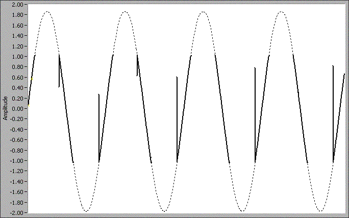
The following figure shows the NI 4070/4071/4072 waveform acquisition overrange behavior. The dotted line represents the actual voltage waveform signal at the input terminals, and the solid line represents the data returned by a waveform acquisition using an NI 4070/4071/4072 in 1 V range. The discontinuities in the solid line waveform represent NaN values in the data, and the spikes in the solid line represent the invalid data as the signal returns to the range limit.
