Burden Voltage
Burden voltage is the voltage drop caused by current flowing through a current measuring device. A large burden voltage can affect the circuit being measured, corrupting the measurement. For this reason, it is desirable for burden voltage to be kept as low as possible.
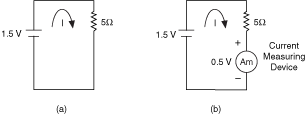
The following figure shows a 1.5 V source with a 5 Ω load. To measure the current on the circuit, an ammeter is connected in series with the circuit. In this figure, the ammeter has a 0.5 V burden voltage.

Without burden voltage (figure a), the calculated current is:
Iactual = 1.5 V / 5 Ω
Iactual = 0.3 A
With burden voltage (figure b), the current in this circuit equals:
Imeasured = (1.5 V-0.5 V ) / (5 Ω)
Imeasured = 0.2 A
In the figure above, burden voltage of the current measuring device subtracts from the voltage across the 5 Ω resistor. The result is a significant error in the measurement. In this case, the error caused by the burden voltage is 33%. Problems like this can easily crop up when using a shunt resistor to measure the current drawn by logic voltages <3.3 V common in today's digital systems.
For the maximum burden voltage per range, refer to Related Documentation for the specifications documents for the DMMs.
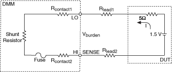
A more complete model of the burden voltage in a DMM is shown in the image below. In this model, you can see that the connections between the DUT and the DMM can also introduce an error into the measurement.

The burden voltage listed in the specifications documents takes into account the voltage drop on the resistance of the ammeter shunt plus the contact and fuse resistances. Usually, the specifications of the DMMs list the maximum burden voltages per range. As a general rule, you should take into account the error introduced by burden voltage if the voltage drop on the source impedance and on the connecting leads is comparable to the burden voltage.
Refer to Related Documentation for the NI 4065 Specifications, the NI 4070/4072 Specifications, and the NI 4071 Specifications, which list the burden voltage specifications.
If the source impedance and leads in your system make the error introduced by the burden voltage relevant, then the measured current is equal to the following equation:
I (5 Ω + RLEAD1 + RLEAD2) + VBURDEN = 1.5 V
Imeasured = (1.5 V - VBURDEN) / (5 Ω + RLEAD1 + R LEAD2)
Recall that the DMM specifications documents list the maximum burden voltage per range. However, if you are measuring at less than full scale, then the actual burden voltage is lower. In this case, you can calculate the actual burden voltage according to the following equation:
Actual VBURDEN = VBURDEN * (Imeasured/Ifull scale),
where Ifull scale corresponds to the current range that you are using
Possible techniques to reduce error caused by ammeter burden voltage include the following:
- When using the current function within the DMM, keep leads to the ammeter short and use the appropriate gauge of cable to minimize voltage drops from leads.
- Sense remotely with external shunts to eliminate the need for long current-carrying cables to the DMM. Use the lowest value of shunt resistance that the measurement allows.
- Use wires in the circuit under test as resistance shunts. Measure the voltage drop across the wire. Then, use the Offset Compensated Ohms feature to measure the resistance of the wire, and calculate I = Vwire/Roco.
 |
Note The NI 4071 has the lowest voltage burden of the NI 4065 and NI 4070/4071/4072 devices. |