Offset Compensated Ohms
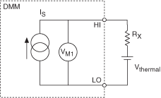
Offset Compensated Ohms is an NI 4070/4071/4072 feature provided for eliminating offset voltages in a resistance test system. Whether 2-wire or 4-wire, Offset Compensated Ohms applies, and the concept is the same. You have learned about the challenges of removing offset resistances from the measurement; however, Offset Compensated Ohms is different—it acts on offset voltages. The measurement involves two cycles as shown in the following figures. The following figure represents the first cycle with the current source ON:

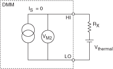
The following figure represents the second cycle with the current source OFF:

The net result is the difference between the two measurements. Because the offset voltage is present in both cycles, it is subtracted out and does not affect the resistance calculation.
VOCO = VM1—VM2 = (ISRX + VTHERMAL)—VTHERMAL = ISRX
therefore:
RX = VOCO/IS
When to Use Offset Compensated Ohms
4-wire measurements provide exceptional accuracy if copper interconnects and low-thermal relays are used in the measurement system. However, there are situations when offset voltages present introduce significant errors:
- Switching systems using uncompensated reed relays can have offset voltages >10 µV due to the Kovar lead material used at the device glass seal.
- In-circuit resistance measurements, for example, power supply conductors being measured for resistance, while the circuit is live.
- Measuring the on-resistance of batteries, dynamic resistance of forward biased diodes, and so on.
In the case of a above, often a test system is built with switching optimized for other things besides resistance measurements. For example, reed relays are common in RF test systems due to their predictable impedance characteristics and high reliability. In such a system you may want to also measure resistances. It might not be economical to add switching hardware for a few channels of resistance, and the RF relays may already be present.
In the case of b, an example would be measuring the resistance of a power supply bus cable. The resistance might be 10 mΩ. If 100 mA is flowing through this resistance, the voltage drop is:
V = 100 mA x 10 mΩ = 1 mV
The DMM without offset compensation on the 100 Ω range interprets this as 1.05 Ω (recall from the table of Source Current and Maximum Test Voltages that 105 Ω corresponds to nominally 100 mV). With the NI 4070/4071/4072 and Offset Compensation, the 1 mV offset is rejected, and the correct value of resistance is returned.
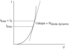
In the case of c above, remember that this test only works if the diode is already forward biased. The NI 4070/4071/4072 does not supply a DC bias to the diode in Offset Compensated Ohms. The NI 4070/4071/4072 does provide the small signal displacement current, but the diode still needs to be biased. The following figure shows this diode example:

To get the dynamic resistance of the diode (or transistor) the selection of the appropriate measurement range is key. NI recommends selecting a range with a corresponding current source value 10% of the bias current level or less.
NI does not recommend using the DMM to directly measure the series resistance of cells greater than 1 V. The NI 4070/4071/4072 does not have enough voltage dynamic range to do this on the lower resistance ranges. Of course, you can use the DMM in conjunction with an external current source or load to do this.
As a general rule for measuring resistances in the presence of large DC offsets, do not violate the following formula, or the results may be erroneous:
Vos+ IsRx = Vt
where
Vos is the offset voltage (what you are trying to compensate out)
Is is the source current (dependent on range, refer to the table above)
Rx is the resistance being measured (or its upper bound)
Vt is the maximum test voltage (from table above)