Resistor Self-Heating
As dissipation of power in a resistor increases, the temperature of the resistor increases and causes a change in the resistance value. You can calculate how much error is introduced in your measurement by resistor self-heating from the derating curve of Rated Power(%) vs. Ambient Temperature commonly given in resistor specifications.
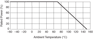
The specifications of resistors include a derating curve, similar to the one shown below. Notice that this curve does not show the temperature change of the resistor due to self-heating. The curve shows the percentage of the rated power that you can apply to a resistor vs. the ambient temperature. So at 70 °C of ambient temperature, you can apply up to 100% of the rated power, but at 100 °C you can only apply up to 65% of the rated power. Refer to the following graph.

At any temperature, the resistor will have a temperature change due to self-heating (which we will refer to as ΔTSH from here on), so the actual temperature of the resistor is the ambient temperature plus an unknown ΔTSH. Even though this graph is not directly showing the value of ΔTSH, it can be calculated from the graph.
Notice that at 70 °C and applying 100% of the rated power, the temperature of the resistor will be equal to 70 °C plus ΔTSH. At 150 °C, you cannot apply any power to the resistor, so the temperature of the resistor is equal to the ambient temperature. You can thus infer that when applying 100% of the rated power at 70 °C the total temperature of the resistor is 150 °C. Therefore, above 70 °C, the value of ΔTSH increases in such a way that when you add to it the ambient temperature it surpasses 150 °C. Therefore, you need to limit the power you apply to the resistor to keep the total temperature of the part under 150 °C. Hence, the value of ΔTSH is a function of the power applied to the part.
The thermal resistance ( ) is therefore equal to the absolute value of the slope between the 70 °C and the 150 °C points in the derating curve shown above.
 = (150 °C—70 °C)/ΔP = (150 °C—70 °C)/Pmax) °C/W
If the resistor has a Rated Power at 70 °C equal to 0.25 W, then the value for  would be equal to:
 = (150 °C—70 °C)/ΔP = (150 °C—70 °C)/250 mW = 80 °C/(250*10–3 W) = 320 °C/W = 0.32 °C/mW
If you want to decrease the thermal resistance, you would need to look for a resistor with higher rated power, or find a way to "heat sink" the resistor to the environment. This however can become complicated and expensive unless the resistor is specifically designed for heat sinking.
You can now calculate the change in temperature due to power dissipation using the thermal resistance ( ) and the power on the resistor (product of voltage and current). Then you can use the temperature coefficient of the resistor (usually given in ppm/ °C) to calculate the change in the resistance value.
Resistor self-heating is more relevant when measuring currents above 100 mA. Resistor self-heating does not present a problem on the NI 4065 and NI 4070/4071/4072, because the internal shunt values are selected for optimum performance. You may observe a settling tail of a few ppm of reading due to self-heating when measuring currents over 100 mA; if this is an issue, increase the settling time of your measurement.