Model
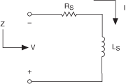
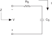
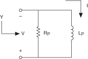
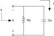
In real-world applications, devices are neither purely reactive nor purely resistive. However, they can be easily modeled either as a series or parallel combination of a resistive and a reactive load using the formulas above.
 |
 |
In general, it is mathematically easier to manipulate parallel loads as admittances and series loads as impedances.
 |
 |
You model the result as a series or parallel model based upon which resistance, RS or RP, is more significant. The parallel resistance (RP) is typically larger than the series resistance (RS). To measure small reactive values, such as high-valued capacitors and low-valued inductors, it is preferable to use the series model, because the series resistance is more significant than the parallel resistance. When measuring large reactive values, such as high-valued inductors or low-valued capacitors, it is preferable to use the parallel model.
| Type of Measurement | Range | Impedance | Model |
|---|---|---|---|
| C | >100 uF | <10 Ω | Series |
| C | 10 nF to 100 uF | 10 Ω to 10 kΩ | Series or parallel |
| C | <10 nF | >10 kΩ | Parallel |
| L | <1 mH | <10 Ω | Series |
| L | 1 mH to 1 H | 10 Ω to 1 kΩ | Series or parallel |
| L | >1 H | ≥1 kΩ | Parallel |
| Note: Impedance values are calculated at the test frequency used on the NI 4072 at each specified range. | |||