Inductors
An inductor is an electronic component that is capable of storing energy as current. Each inductor consists of a conductive coil that can be wrapped without a core or around a magnetic material. The permeability of the core material is a measure of the intensity of the magnetic field that can be induced in it.
The electrical properties of the cores show variability with factors such as temperature, frequency, current, and so on. This variability and the mechanical construction of the inductor create a less than ideal device.
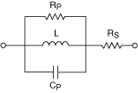
A better representation of real-world inductors is shown in the equivalent model below, which aids in understanding the different parasitic elements that are present in a real-world component. These parasitic elements impact the inductor impedance at different test frequencies.

The series resistance, Rs, represents the resistive losses in the conductor. The parallel capacitance, Cp, is the equivalent capacitive effect between the turns of the coil, and the parallel resistance, Rp, is the sum of all losses attributable to the core material.
Air cores require many more turns in the coil to achieve high-inductance values. Thus, air cores are often impractical for applications, due to their large size and weight. Also, air cores usually have a large winding capacitance and a series resistance with a high-inductance value.
Not all parasitics affect the value of the inductor, but some parasitics are more prominent than others, depending upon the construction of the coil, the geometry of the inductor, the gauge of the wire, and the characteristics of the core. The value of the inductor and the magnitude of each type of parasitic in relation to the other types of parasitics determine the frequency response.
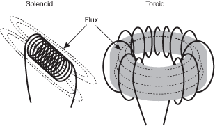
The geometry of some components can increase the sensitivity of the components to external factors, and this increased sensitivity can also affect the value of the inductor. Open flux inductors are more sensitive to metallic materials that are in close proximity, because such materials modify the magnetic field. Toroidal inductors keep the flux inside the core and are less sensitive to external conductors in close proximity. Refer to the following figure to view the flux associated with these types of inductors:

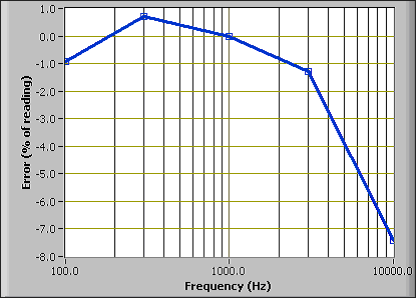
In the following graph, a 5 mH air-core inductor is measured over different frequencies. The error is referenced to the measurement with a test signal of 1 Vrms at 1 kHz. This type of inductor has a high degree of winding capacitance due to the size and number of turns required for its construction. Therefore, this type of inductor measures as if there were a strong variation of inductance with frequency.

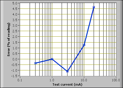
Some ferrite cores are expected to vary greatly with the test signal level. In the following graph, a 100 uH ferrite-core inductor is tested at different test signal levels. The error is referenced to the measurement with a test signal of 1 mArms at 1 kHz.

All of these factors can combine and cause inductors to have different values under varying conditions of temperature, frequency, and signal level.