4-Wire Resistance Measurements
For precision measurements with resistances below 100 kΩ, the 4-wire mode is more accurate than the 2-wire mode. The 4-wire mode requires 4-wire switching and more cabling; however, you may decide the tradeoff is acceptable, depending upon the accuracy versus complexity requirements of your system.
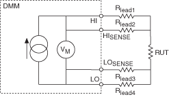
The following figure shows a 4-wire resistance measurement, including lead resistance:

In 4-wire resistance measurements, current is forced through the source terminals (HI, LO). The sense terminals (HISENSE, LOSENSE) are configured for very high impedance, and this configuration directs current through the resistance under test (RUT). As a result, voltage develops across RUT as well as across RLEAD1 and RLEAD4. By measuring the voltage directly across RUT using the sense leads (RLEAD2, RLEAD3), the voltage drop of the source leads (RLEAD1, RLEAD4) is removed from the measurement path.
The current source in the NI 4065 and NI 407x devices, and any of the current sources used in resistance measurements, have limited voltages that they can withstand. To avoid damage to the DMM, refer to the NI Product Manuals Library Web site for the specifications document for the DMM that you are using; this document lists the maximum 4-wire lead resistance, which is the maximum resistance that can occur in the source leads (RLEAD1, RLEAD4) that connect HI and LO terminals to RUT.
A maximum 4-wire lead resistance that is specified as the lesser of 10% of range or 1 kΩ implies that the maximum 4-wire lead resistance (RLEAD1 + RLEAD4) is within these limits.
For example, if you are using the 100 kΩ resistance range, 10% of this range is 10 kΩ. Therefore, the maximum 4-wire lead resistance (RLEAD1 + RLEAD4) is 1 kΩ.