Resistance Temperature Detector (RTDs)

An RTD, or Resistance Temperature Detector, is a temperature sensing device with resistance that increases with temperature. An RTD is usually constructed with wire coil or deposited film of pure metal. RTDs can be made of different metals and have different nominal resistances, but the most popular RTD is platinum and has a nominal resistance of 100 Ω at 0 °C.
Numerous types of RTDs exist, and they are typically defined by their material, their nominal resistance, and their temperature coefficient of resistance (TCR). The TCR, or α, of an RTD is the average temperature coefficient of resistance of the RTD from 0 to 100 °C and is the most common method of specifying the behavior of an RTD. The TCR for platinum RTDs is determined by the Callendar-Van Dusen equation.
The Callendar-Van Dusen equation is as follows:
Temperatures below 0 °C:
RT = R0[1 + A × T + B × T2 + C × T3 × (T – 100 °C)]
Temperatures above 0 °C:
RT = R0[1 + A × T + B × T2]
T = temperature in degrees Celsius
RT = RTD resistance at temperature T
R0 = RTD nominal resistance at 0 °C
A, B, and C = coefficients listed in the following table.
The following table lists common platinum RTD types and standards supported in NI-DMM. Notice that there are some shared standards. The TCR and the Callendar-Van Dusen coefficients are more important than the standards. NI-DMM also supports user-specified A, B, and C coefficients through the custom RTD type if none of the presets below match the transducer.
| Standards | Material | TCR (α) | Typical R0 (Ω) | Callendar-Van Dusen Coefficient | Notes |
|---|---|---|---|---|---|
| IEC-751 DIN 43760 BS 1904 ASTM-E1137 EN-60751 |
Platinum | .003851 | 100 Ω 1000 Ω |
A = 3.9083 × 10⁻³ B = –5.775×10⁻⁷ C = –4.183×10⁻¹² |
Most common RTDs |
| Low-cost vendor compliant RTD* | Platinum | .003750 | 1000 Ω | A = 3.81 × 10⁻³ B = –6.02×10⁻⁷ C = –6.0×10⁻¹² |
Low-cost RTD |
| JISC 1604 | Platinum | .003916 | 100 Ω | A = 3.9739 × 10⁻³ B = –5.870×10⁻⁷ C = –4.4 ×10⁻¹² |
Used primarily in Japan |
| US Industrial Standard D-100 American |
Platinum | .003920 | 100 Ω | A = 3.9787 × 10⁻³ B = –5.8686×10⁻⁷ C = –4.167 ×10⁻¹² |
Low-cost RTD |
| US Industrial Standard American |
Platinum | .003911 | 100 Ω | A = 3.9692 × 10⁻³ B = –5.8495×10⁻⁷ C = –4.233 ×10⁻¹² |
Low-cost RTD |
| ITS-90 | Platinum | .003928 | 100 Ω | A = 3.9888 × 10⁻³ B = –5.915×10⁻⁷ C = –3.85 ×10⁻¹² |
The definition of temperature |
| *No standard. Check the TCR. | |||||
 |
Note For more information on taking temperature measurements with an RTD, refer to the NI Developer Zone document, Measuring Temperature with an RTD or Thermistor. |
Cabling
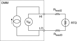
2-Wire RTD measurements are wired using the HI and LO connectors of the DMM:

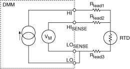
To use a 3-Wire RTD configuration in a 4-wire RTD, jumper the negative end of the current excitation connection to the negative end of the voltage measurement connection. This configuration decreases the effect of lead resistance on the measurement, however, Rlead3 will still contribute some error, depending on its resistance:

 |
Note You must configure your NI-DMM using a 4-wire connection for 3-wire measurements. |
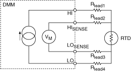
4-Wire RTD measurements are wired using the HI, LO, HISENSE, and LOSENSE connectors of the DMM. This configuration minimizes the effects of lead resistance:

Underlying DMM Measurement
To measure temperature with an RTD, the DMM performs a 2-Wire or 4-Wire resistance measurement with the range, resolution, timing, and other measurement options that have been specified by the user. The resulting resistance is then converted to degrees Celsius by software using the Callendar-Van Dusen equation and R0, A, B, and C coefficients.
When configuring a temperature transducer measurement, the user must specify the range and resolution of the underlying voltage or resistance measurement while configuring the DMM. The recommended range for a 100 Ω RTD is 1 kΩ and the recommended range for a 1 kΩ RTD is 10 kΩ.
Self-Heating
There is an I2R power dissipated by the RTD that causes self-heating. Self-heating will actually change the resistance of the RTD, causing error in the measurement. RTDs are prone to self-heating because they require current excitation. The effects of self-heating can be minimized by supplying lower excitation current.
Typically, a dissipation constant is provided in RTD specifications. This number relates the power required to raise the RTD temperature by one degree of temperature. Thus, a 25-mW/°C dissipation constant shows that if I2R power losses in the RTD equal 25 mW, then the RTD will be heated by 1 °C.
The dissipation constant is usually specified under two conditions free air and a well-stirred oil bath. This is because of the difference in capacity of the medium to carry heat away from the device. The self-heating temperature rise can be found from the power dissipated by the RTD and the dissipation constant from

where
DT = temperature rise because of self-heating in °C
P = power dissipated in the RTD from the circuit in W
PD = dissipation constant of the RTD in W/°C
Refer to Resistor Self-Heating for more information.