Topologies
A switch topology is an organizational representation of the channels and relays in a switch module. The topology establishes the default states for all relays in a module and defines the channel names. Some switches can use multiple topologies or variations of each topology type. Some terminal blocks or accessories may force the switch to use a given topology or set of topologies.
NI switches use three categories of topologies:
General-Purpose Topologies
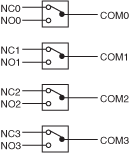
General-purpose topologies consist of multiple isolated relays. Each channel of a general-purpose switch module can connect one input to one output. They are typically used to power ON or OFF devices such as motors, fans, and lights or to switch high-voltage or high-current signals.

Multiplexer
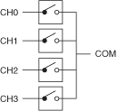
A multiplexer, or a MUX, is a topology in which you can connect one input to multiple outputs or one output to multiple inputs. This topology is often used for scanning when you need to automatically connect a sequence of channels to a common line.
| 4x1 Multiplexer Composed of Form A Relays | 4x1 Multiplexer Composed of Form C Relays |
|---|---|
 |  |
Matrix
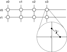
A matrix is one of the most flexible switching configurations. Unlike a multiplexer, a matrix can connect multiple inputs to multiple outputs organized as columns and rows. You can connect any column to any number of rows and any row to any number of columns. At each intersection of a row and column, there is a switch. When the switch is closed, the row is connected to the column.
Matrix size is often described as M rows by N columns (M x N). The figure below depicts a 1-wire, 2 x 4 matrix, where cn is any device under test (DUT) and rn is any of the instruments, including the DMM.
