Switching Voltages
When switching high-voltage signals, the parasitic capacitance of the cable connecting the NI 4065 and NI 4070/4071/4072 with the switches, as well as the input capacitance of the instrument, need to be charged to the source voltage. Depending on the voltage present at the DMM input during the measurement on the previous channel, a significant current can flow from the high–voltage source to charge this capacitance. This action is referred to as hot switching, which can reduce the life of the switches. Refer to your switch documentation for information about extending switch life.
When switching high-voltage signals into a low-voltage range of any DMM (such as applying 300 V on the 10 V range), the input impedance will be lower than it is when the proper range is selected. Repetitive operations like this may shorten switch life. To maximize switch life, always select a measurement range that can handle the maximum voltage expected.
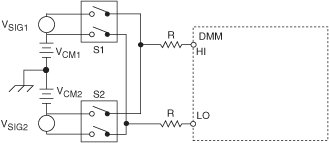
Switching signals with large common-mode components (LO switched from +250 V to -250 V) may, over extended periods of time (tens of Hz for several weeks) begin to degrade the relay performance. The switching life of the relays can be extended in many cases by inserting some small common-mode resistance in series with the LO terminals. Even several hundred ohms (200 to 500 Ω) helps significantly. Refer to the following figure, where VCM1 or VCM2 >50 V:

In these situations, break-before-make switching is essential to obtaining any kind of reliable relay life. Should S1 and S2 be turned on together, even momentarily, VCM1 + VSIG1, is shorted to VCM2 + VSIG2, which could cause high currents to permanently damage the contacts of S1 or S2.