2-Wire Resistance Measurements
The 2-wire method is commonly used as it is the simplest and most straightforward method. Using the 2-wire method, you can get accurate measurements above 100 kΩ relatively easily. For lower resistance values, such as 100 Ω, the interconnecting cabling can add significant resistance which can greatly affect your measurement. Copper is the most common and is the recommended cabling. Copper has a temperature coefficient in the 3,000 ppm/°C range, which can add instability to the measurement. NI recommends the Belden 83317E cable, which has excellent shielding and insulation resistance qualities and a resistance of 39 mΩ/ft. Refer to the Belden CDT Incorporated Web site at www.belden.com for information about this cable.
When considering cabling, refer to the following example:
Assume that a test system has 50 feet of copper interconnect cable hooked to a single 100 Ω resistance, such as a remote sensor device, the cable could easily introduce a resistance of ~2 Ω because Belden 83317E has a resistance of 40 mΩ/ft and 50 ft x 40 mΩ/ft = 2 Ω. The temperature coefficient of the resistance is as follows:
TC = 2Ω x 3,000 ppm/°C = 6 mΩ/°C
Relative to the 100 Ω resistance being measured:
TC = (6 mΩ/°C)/(100 Ω) = 60 ppm/°C
The error introduced by the copper not only affects the initial value of resistance measured but also introduces a temperature drift into the measurement. The drift with temperature of the copper resistance (60 ppm/°C in the example above) is much larger than the drift of the resistance ranges of the NI 4065 and NI 4070/4071/4072 (well under 10 ppm/°C). Recognize, however, that this drift might be perfectly acceptable to the particular measurement being made. Temperature drifts should be considered in the system error budget.
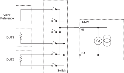
Sometimes the leads can be locally shorted, a measurement made, and then this "offset" and its associated TC subtracted from the subsequent 2-wire resistance measurement on the resistors under test. This technique works with careful experimental measurement practice. An outline of the methodology for this technique in the context of an automated measurement system, with programmable switching available, is as follows:
- Short the leads as close to the resistance under test
as possible. If the measurement is part of an automated switching system,
dedicate a switch channel to a zero value. During the measurement cycle, close
the switch to the zero reference. Refer to the following figure.

- Record the offset of this zero channel.
- Switch to the resistance channel you want to use.
- Measure the resistance value.
- Subtract the offset value from the resistance value on the selected channel. The result is the resistance reading you want.
This method is subject to the following caveats:
- If the zero relay has a different contact-resistance than the rest of the relays, an error is introduced.
- If possible, you should terminate the zero channel with a cable very close in length to those cables leading to the resistance under test, matching the path length as closely as possible.
- This method does not correct for the lead resistance of the component you are testing.
- A time penalty occurs in the system and is associated with closing the zero relay and taking the additional measurement.
- The stability of the relay ON-resistance may limit this method to a repeatability of about ±20 mΩ.