AC Voltage
AC signals are typically characterized by their root-mean-square (rms) amplitude, which is a measure of their total energy. To compute the rms value of a waveform, you must take the square root of the mean value of the square of the signal level. Most DMMs, including the NI 4050, NI 4060, and NI 4065, do this nonlinear signal processing in the analog domain, but the NI 4070/4071/4072 uses an onboard digital signal processor (DSP) to compute the rms value from digitized samples of the AC waveform. By computing rms values (a traditionally analog problem) in the digital domain using the DSP chip, the NI 4070/4071/4072 speeds up AC measurements in two ways, as follows:
- Allows computation of fully-settled RMS values with only four cycles of the waveform
- Automatically rejects the DC component of the signal, making possible an AC Volts DC Coupled mode, which completely bypasses the slow-setting input coupling capacitor required on traditional DMMs
The result is quiet, accurate, and fast-settling AC readings.
The rms algorithm used by the NI 4070/4071/4072 requires at least 4 cycles of the waveform to obtain a quiet reading. For example, it requires a measurement aperture of 4 ms to accurately measure a 1 kHz sine wave. The measurement aperture also needs to be long enough to obtain the requested resolution. For example, although a 40 µs aperture is long enough to measure the rms value of a 100 kHz sine wave, it is not long enough to obtain readings with 6½ digit accuracy. Thus, the period of the waveform being measured and the desired resolution both affect the necessary aperture. NI-DMM selects the shortest aperture to satisfy both requirements. Refer to the Measurement Defaults table for the aperture times used by the NI 4070/4071/4072, or to the Measurement Defaults table for for the aperture times used by the NI 4065.
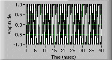
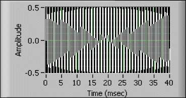
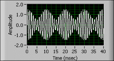
It is important to realize that it is the period of the measured waveform, and not the period of its lowest-frequency component, that determines the required minimum aperture as shown in Figures A, B, and C. Figure A shows a 1 kHz sine wave. That signal could be measured in 4 ms because that is 4 cycles of the waveform. Figure B shows a 1.1 kHz sine wave. It too could be measured in 4 ms because that is slightly more than 4 cycles of the waveform. Figure C shows a signal that is simply the sum of the signals in Figures A and B. Although the minimum frequency component of that signal is 1 kHz, 4 msec is clearly not long enough to measure the rms value of the whole signal. In this case, the signal has a period of 10 msec, so it requires a 40 msec aperture for an accurate measurement.
Figure A

Figure B

Figure C
