Measuring on the 100 MΩ Range
The 100 MΩ range provides a unique capability, allowing measurements up to 1.05 GΩ (NI 4065 and NI 4070/4072) or 5 GΩ (NI 4071), because of the methodology of the measurement and the high–impedance design of the NI 4065 and NI 4070/4071/4072. This range allows 2-wire operation only, and Offset Compensated Ohms cannot be enabled.
It is difficult to get a meaningful measurement with resistances above 10 MΩ without good shielding—including shielding of the resistor under test. Enclose the resistor under test in a metallic box, and connect this enclosure to LO terminal. In the laboratory, even a small box covered with a single, continuous sheet of aluminum foil helps significantly with this kind of measurement.
Noise
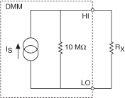
The following diagram shows an equivalent circuit for all measurements above the 10 MΩ range.

The voltage across the resistor is measured by the NI 4056 and NI 4070/4071/4072 and the resistor is calculated from:
Rx = V /(Is—(V/10 MΩ)
where
Rx = the resistor under test (up to 1.05 GΩ on the NI 4065 and NI 4070/4072, or up to 5 GΩ on the NI 4071)
V = the voltage measured by the DMM with Rx applied
Is = the source current (nominally 0.95 uA)
For 100 MΩ to 1 GΩ (NI 4065 and NI 4070/4072) or for 100 MΩ to 5 GΩ (NI 4071), consider the following:
- The ADC only uses 10% of its range. Typical accuracy values are in the 5% range.
- Any environmental noise or interference is amplified as the resistance being measured is increased. The requirement for good shielding increases as the resistor value increases.
The Johnson noise of the resistor is always a factor in the measurement. Calculating from the equation described in Noise, the Johnson noise of typical high MΩ resistors is listed below in ppm of reading, assuming a bandwidth of 10 Hz (roughly equivalent to a 100 ms aperture time)
Measurements above 10 MΩ should be made with as long an aperture time as possible, and 100 ms is the minimum recommended value. High-order DC noise rejection is recommended.
Johnson Noise of Various High–Value Resistors
| Resistor Value | Johnson Noise1 (Vp–p) (10 Hz bandwidth at 23 °C) |
|---|---|
| 10 MΩ | 8 µV |
| 30 MΩ | 15 µV |
| 100 MΩ | 27 µV |
| 300 MΩ | 46 µV |
| 1 GΩ | 85 µV |
| 5 GΩ | 189 µV |
| 1Represents the "ideal" noise due to the Johnson noise of the resistor. Actual noise may be higher, due to environment, poor shielding, and so on. | |