This polymorphic instance calculates
and reports PSK quadrature impairments on a symbol-by-symbol basis at the symbol
timing.
 |
PSK system parameters specifies parameter values defining the PSK system. Wire the
PSK system parameters cluster from the PSK (M) or PSK (Map) instance of the MT Generate System Parameters VI to this cluster. Do not
alter the values.
 |
samples per symbol specifies an even, positive number of samples dedicated to
each symbol. Multiply this value by the symbol rate to determine the sample
rate. The default is 16.
|
 |
symbol map specifies an ordered array that maps each Boolean symbol to its
desired coordinates in the complex plane. The number of states in the array must
be 2N, where N is the number of bits per symbol.
|
 |
differential PSK specifies how the PSK modulation represents symbols. Differential
operation is used to implement PSK formats such as differential quadrature PSK
(DQPSK) and  /4-DQPSK. /4-DQPSK.
| disable (0) |
Symbols are represented as constellation points. This is the default value.
|
| enable (1) |
Symbols are represented as the transitions between constellation points.
|
|
 |
PSK type specifies the type of PSK modulation.
|
normal
|
Sets the modulation type to regular PSK. This is the default value. |
|
shifted
|
Rotates the constellation by /M each
symbol. |
|
offset
|
Sets the modulation type to offset quadrature phase-shift keying (OQPSK). This modulation scheme is a form of phase-shift keying in which four different phase angles are used. This scheme is sometimes referred to as staggered quadrature phase-shift keying (SQPSK). For offset PSK, the ideal symbol timing for Q is offset by 1/2 of a
symbol period from the ideal symbol timing for I. offset is currently only
supported for M = 4.
|
|
|
|
recovered complex waveform specifies the time-aligned and oversampled complex waveform
data after matched filtering, frequency offset correction, and phase offset
correction. Wire the recovered complex waveform parameter of the MT Demodulate PSK VI to this parameter.
 |
t0 specifies the trigger (start) time of the Y array. The default is 0.0.
|
|
dt specifies the time interval between data points in the Y array. The default is 1.0.
|
|
Y specifies the complex-valued signal-only baseband modulated
waveform. The real and imaginary parts of this complex data array correspond to
the in-phase (I) and quadrature-phase (Q) data, respectively.
|
|
 |
input bit stream specifies the demodulated bit stream from the output bit stream parameter of the MT Demodulate PSK VI.
|
 |
impairment measurement window specifies the window over which impairments are measured.
|
start index specifies the index of the first sample of the measurement
window. The default is 0.
|
|
width specifies the number of symbols over which to measure
impairments. A value of -1 (default) measures
impairments over all symbols. Positive values must be two or greater.
|
|
|
impairment definition specifies which set of equations is used to represent impairments.
In the equations in the following table,
I is the real component and Q
is the imaginary component of each sample in the input complex waveform.
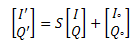
I' and Q' are the real and imaginary components
of the corresponding sample in the output complex waveform,
I
° is I DC Offset (%) / 100,
and Q
° is Q DC Offset (%) / 100.
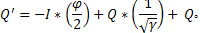
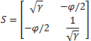
| Vertical Shear (0) |
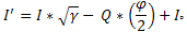
The definition uses the following equations for I/Q impairments:
I' = a * I + I
°
Q' = a * sin(φ) * I + b * cos(φ) * Q + Q
°
where
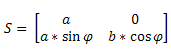
φ = the specified quadrature skew, in radians
 = 10(IQ gain imbalance/20) = 10(IQ gain imbalance/20)
a = * b
b = 
In matrix form, these equations are represented by
where
|
| Axis Shear (1) |
With this option selected, this VI uses an impairment definition that simplifies the conversion between measured impairments and their inverse impairments. For example, you may want to measure the I/Q impairments of a system and compensate for those impairments by applying the inverse impairments to the generated or received waveform. Using the Axis Shear definition, given a measured skew and imbalance (in dB), the inverse impairments are –1.0 * skew and –1.0 * imbalance. This definition uses the following equations for IQ impairments:
where
= 10(IQ gain imbalance/20)
φ = the specified quadrature skew, in radians
In matrix form, these equations are represented by
where
|
|
 |
reset? specifies how the VI handles bits from partial symbols in the
input bit stream. When reset? is set to TRUE, bits making up incomplete symbols are
discarded. When reset? is set to FALSE, the VI
saves the leftover bits and starts with them on the next iteration. The default is TRUE.
|
|
error in (no error) can accept error information wired from
previously called VIs. Use this information to decide if any functionality
should be bypassed in the event of errors from other VIs. Right-click the front
panel error in control and select Explain Error or Explain
Warning from the shortcut menu for more information about the error.
|
status is TRUE (X) if an error occurred or FALSE (checkmark) to
indicate a warning or that no error occurred. Right-click the front panel
error in control and select Explain Error or Explain
Warning from the shortcut menu for more information about the
error.
|
|
code identifies the error or warning code. Right-click the front
panel error in control and select Explain Error or Explain
Warning from the shortcut menu for more information about the
error.
|
 |
source describes the origin of the error or warning. Right-click the
front panel error in control and select Explain Error or Explain
Warning from the shortcut menu for more information about the
error.
|
|
 |
IQ gain imbalance returns the measured ratio of I gain to Q gain, in dB.
 |
Tip For shifted BPSK (also called /2 BPSK with or without
differential encoding), certain measurements, including IQ
gain imbalance, quadrature skew, and
DC offset measurements, are not performed by
the current version of the Modulation Toolkit. The current version of the
Modulation Toolkit returns NaN in these
cases. Other measurements, specifically modulation error
ratio, error vector magnitude,
magnitude error, and phase
error, are valid and returned for shifted (/2)
BPSK. |
|
 |
phase error returns the measured phase error in degrees. Notice that the phase offset is removed by the
demodulator and is excluded from this measurement.
|
RMS measurement returns the rms impairment value calculated over the
impairment measurement window.
|
|
peak measurement returns the peak impairment value measured over the
impairment measurement window.
|
 |
peak symbol index returns the index of the symbol having the peak magnitude of
impairment.
|
 |
individual symbol measurements returns the impairment value for each individual symbol.
|
|
|
EVM returns the measured error
vector magnitude (EVM) expressed as a percentage.
|
RMS measurement returns the rms impairment value calculated over the
impairment measurement window.
|
|
peak measurement returns the peak impairment value measured over the
impairment measurement window.
|
|
peak symbol index returns the index of the symbol having the peak magnitude of
impairment.
|
|
individual symbol measurements returns the impairment value for each individual symbol.
|
|
|
modulation error ratio returns the measured modulation error ratio in dB.
|
|
magnitude error returns the measured magnitude error as a percentage of full
scale. Magnitude error is the magnitude difference between the ideal and the
actual measured symbol locations.
|
RMS measurement returns the rms impairment value calculated over the
impairment measurement window.
|
|
peak measurement returns the peak impairment value measured over the
impairment measurement window.
|
|
peak symbol index returns the index of the symbol having the peak magnitude of
impairment.
|
|
individual symbol measurements returns the impairment value for each individual symbol.
|
|
 |
DC offset measurements returns the measured DC offset of the I or Q waveforms as a percentage of the largest I and Q value in the symbol map
of the recovered complex waveform.
|
I returns the DC offset of the I waveform, expressed as a
percentage of the largest I or Q value in the symbol map.
|
|
Q returns the DC offset of the Q waveform, expressed as a
percentage of the largest I or Q value in the symbol map.
|
|
origin offset returns the offset, in dB, of the constellation origin from its
ideal location.
|
|
|
quadrature skew returns the measured quadrature skew of the complex waveform in degrees.
|
|
error out passes error or warning information out of a VI to be used by
other VIs. Right-click the front panel error out indicator and select
Explain Error or Explain
Warning from the shortcut menu for more information about the
error.
 |
status is TRUE (X) if an error occurred or FALSE (checkmark) to
indicate a warning or that no error occurred. Right-click the front panel
error out indicator and select Explain Error or Explain
Warning from the shortcut menu for more information about the
error.
|
|
code is the error or warning code. Right-click the front panel
error out indicator and select Explain Error or Explain
Warning from the shortcut menu for more information about the
error.
|
 |
source describes the origin of the error or warning. Right-click the
front panel error out indicator and select Explain Error or Explain
Warning from the shortcut menu for more information about the
error.
|
|
|
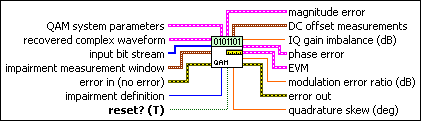
recovered complex waveform specifies the time-aligned and oversampled complex waveform
data after matched filtering, frequency offset correction, and phase offset
correction. Wire the recovered complex waveform
parameter of the MT Demodulate QAM VI to this parameter.
|
t0 specifies the trigger (start) time of the Y array. The default is 0.0.
|
|
dt specifies the time interval between data points in the Y array. The default is 1.0.
|
|
Y specifies the complex-valued signal-only baseband modulated
waveform. The real and imaginary parts of this complex data array correspond to
the in-phase (I) and quadrature-phase (Q) data, respectively.
|
|
|
input bit stream specifies the demodulated bit stream from the output bit stream parameter of the MT Demodulate QAM VI.
|
|
impairment measurement window specifies the window over which impairments are measured.
|
start index specifies the index of the first sample of the measurement
window. The default is 0.
|
|
width specifies the number of symbols over which to measure
impairments. A value of -1 (default) measures
impairments over all symbols. Positive values must be two or greater.
|
|
|
QAM system parameters specifies parameter values defining the QAM system. Wire the
QAM system parameters cluster returned by the QAM (M) or QAM (Map) instance of the MT Generate System Parameters VI to this cluster. Do
not alter the values.
|
samples per symbol specifies an even, positive number of samples dedicated to
each symbol. Multiply this value by the symbol rate to determine the sample
rate. The default is 16.
 |
Note The Modulation Toolkit demodulation and detector VIs use timing recovery, which is optimized for four or more samples per symbol. |
|
|
symbol map specifies an ordered array that maps each symbol value to its
desired coordinates in the complex plane. The number of QAM states in the array
must be 2N, where N is the number of bits per symbol. The length of
the vector for the symbol(s) farthest from the origin must be 1.
|
|
|
impairment definition specifies which set of equations is used to represent impairments.
In the equations in the following table,
I is the real component and Q
is the imaginary component of each sample in the input complex waveform.
I' and Q' are the real and imaginary components
of the corresponding sample in the output complex waveform,
I
° is I DC Offset (%) / 100,
and Q
° is Q DC Offset (%) / 100.
| Vertical Shear (0) |
The definition uses the following equations for I/Q impairments:
I' = a * I + I
°
Q' = a * sin(φ) * I + b * cos(φ) * Q + Q
°
where
φ = the specified quadrature skew, in radians
= 10(IQ gain imbalance/20)
a = * b
b =
In matrix form, these equations are represented by
where
|
| Axis Shear (1) |
With this option selected, this VI uses an impairment definition that simplifies the conversion between measured impairments and their inverse impairments. For example, you may want to measure the I/Q impairments of a system and compensate for those impairments by applying the inverse impairments to the generated or received waveform. Using the Axis Shear definition, given a measured skew and imbalance (in dB), the inverse impairments are –1.0 * skew and –1.0 * imbalance. This definition uses the following equations for IQ impairments:
where
= 10(IQ gain imbalance/20)
φ = the specified quadrature skew, in radians
In matrix form, these equations are represented by
where
|
|
|
reset? specifies how the VI handles bits from partial symbols in the
input bit stream. When reset? is set to TRUE, bits making up incomplete symbols are
discarded. When reset? is set to FALSE, the VI
saves the leftover bits and starts with them on the next iteration. The default is TRUE.
|
|
error in (no error) can accept error information wired from
previously called VIs. Use this information to decide if any functionality
should be bypassed in the event of errors from other VIs. Right-click the front
panel error in control and select Explain Error or Explain
Warning from the shortcut menu for more information about the error.
|
status is TRUE (X) if an error occurred or FALSE (checkmark) to
indicate a warning or that no error occurred. Right-click the front panel
error in control and select Explain Error or Explain
Warning from the shortcut menu for more information about the
error.
|
|
code identifies the error or warning code. Right-click the front
panel error in control and select Explain Error or Explain
Warning from the shortcut menu for more information about the
error.
|
|
source describes the origin of the error or warning. Right-click the
front panel error in control and select Explain Error or Explain
Warning from the shortcut menu for more information about the
error.
|
|
|
IQ gain imbalance returns the measured ratio of I gain to Q gain, in dB.
|
|
phase error returns the measured phase error in degrees. Notice that the phase offset is removed by the
demodulator and is excluded from this measurement.
|
RMS measurement returns the rms impairment value calculated over the
impairment measurement window.
|
|
peak measurement returns the peak impairment value measured over the
impairment measurement window.
|
|
peak symbol index returns the index of the symbol having the peak magnitude of
impairment.
|
|
individual symbol measurements returns the impairment value for each individual symbol.
|
|
|
EVM returns the measured error
vector magnitude (EVM) expressed as a percentage.
|
RMS measurement returns the rms impairment value calculated over the
impairment measurement window.
|
|
peak measurement returns the peak impairment value measured over the
impairment measurement window.
|
|
peak symbol index returns the index of the symbol having the peak magnitude of
impairment.
|
|
individual symbol measurements returns the impairment value for each individual symbol.
|
|
|
modulation error ratio returns the measured modulation error ratio in dB.
|
|
magnitude error returns the measured magnitude error as a percentage of full
scale. Magnitude error is the magnitude difference between the ideal and the
actual measured symbol locations.
|
RMS measurement returns the rms impairment value calculated over the
impairment measurement window.
|
|
peak measurement returns the peak impairment value measured over the
impairment measurement window.
|
|
peak symbol index returns the index of the symbol having the peak magnitude of
impairment.
|
|
individual symbol measurements returns the impairment value for each individual symbol.
|
|
|
DC offset measurements returns the measured DC offset of the I or Q waveforms as a percentage of the largest I and Q value in the symbol map
of the recovered complex waveform.
|
I returns the DC offset of the I waveform, expressed as a
percentage of the largest I or Q value in the symbol map.
|
|
Q returns the DC offset of the Q waveform, expressed as a
percentage of the largest I or Q value in the symbol map.
|
|
origin offset returns the offset, in dB, of the constellation origin from its
ideal location.
|
|
|
quadrature skew returns the measured quadrature skew of the complex waveform in degrees.
|
|
error out passes error or warning information out of a VI to be used by
other VIs. Right-click the front panel error out indicator and select
Explain Error or Explain
Warning from the shortcut menu for more information about the
error.
|
status is TRUE (X) if an error occurred or FALSE (checkmark) to
indicate a warning or that no error occurred. Right-click the front panel
error out indicator and select Explain Error or Explain
Warning from the shortcut menu for more information about the
error.
|
|
code is the error or warning code. Right-click the front panel
error out indicator and select Explain Error or Explain
Warning from the shortcut menu for more information about the
error.
|
|
source describes the origin of the error or warning. Right-click the
front panel error out indicator and select Explain Error or Explain
Warning from the shortcut menu for more information about the
error.
|
|
|
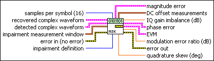
recovered complex waveform specifies the time-aligned and oversampled complex waveform
data after matched filtering, frequency offset correction, and phase offset
correction. Wire the recovered complex waveform
parameter of the MT Demodulate MSK VI to this parameter.
|
t0 specifies the trigger (start) time of the Y array. The default is 0.0.
|
|
dt specifies the time interval between data points in the Y array. The default is 1.0.
|
|
Y specifies the complex-valued signal-only baseband modulated
waveform. The real and imaginary parts of this complex data array correspond to
the in-phase (I) and quadrature-phase (Q) data, respectively.
|
|
|
detected complex waveform specifies the ideal oversampled waveform. Wire the detected complex waveform parameter of the MT Demodulate MSK VI to this parameter.
|
t0 specifies the trigger (start) time of the Y array. The default is 0.0.
|
|
dt specifies the time interval between data points in the Y array. The default is 1.0.
|
|
Y specifies the ideal oversampled waveform as a complex-valued
array.
|
|
|
impairment measurement window specifies the window over which impairments are measured.
|
start index specifies the index of the first sample of the measurement
window. The default is 0.
|
|
width specifies the number of symbols over which to measure
impairments. A value of -1 (default) measures
impairments over all symbols. Positive values must be two or greater.
|
|
|
samples per symbol specifies the number of samples per symbol in the modulated complex waveform. The default is 16.
|
|
impairment definition specifies which set of equations is used to represent impairments.
In the equations in the following table,
I is the real component and Q
is the imaginary component of each sample in the input complex waveform.
I' and Q' are the real and imaginary components
of the corresponding sample in the output complex waveform,
I
° is I DC Offset (%) / 100,
and Q
° is Q DC Offset (%) / 100.
| Vertical Shear (0) |
The definition uses the following equations for I/Q impairments:
I' = a * I + I
°
Q' = a * sin(φ) * I + b * cos(φ) * Q + Q
°
where
φ = the specified quadrature skew, in radians
= 10(IQ gain imbalance/20)
a = * b
b =
In matrix form, these equations are represented by
where
|
| Axis Shear (1) |
With this option selected, this VI uses an impairment definition that simplifies the conversion between measured impairments and their inverse impairments. For example, you may want to measure the I/Q impairments of a system and compensate for those impairments by applying the inverse impairments to the generated or received waveform. Using the Axis Shear definition, given a measured skew and imbalance (in dB), the inverse impairments are –1.0 * skew and –1.0 * imbalance. This definition uses the following equations for IQ impairments:
where
= 10(IQ gain imbalance/20)
φ = the specified quadrature skew, in radians
In matrix form, these equations are represented by
where
|
|
|
error in (no error) can accept error information wired from
previously called VIs. Use this information to decide if any functionality
should be bypassed in the event of errors from other VIs. Right-click the front
panel error in control and select Explain Error or Explain
Warning from the shortcut menu for more information about the error.
|
status is TRUE (X) if an error occurred or FALSE (checkmark) to
indicate a warning or that no error occurred. Right-click the front panel
error in control and select Explain Error or Explain
Warning from the shortcut menu for more information about the
error.
|
|
code identifies the error or warning code. Right-click the front
panel error in control and select Explain Error or Explain
Warning from the shortcut menu for more information about the
error.
|
|
source describes the origin of the error or warning. Right-click the
front panel error in control and select Explain Error or Explain
Warning from the shortcut menu for more information about the
error.
|
|
|
IQ gain imbalance returns the measured ratio of I gain to Q gain, in dB.
|
|
phase error returns the measured phase error in degrees. Notice that the phase offset is removed by the
demodulator and is excluded from this measurement.
|
RMS measurement returns the rms impairment value calculated over the
impairment measurement window.
|
|
peak measurement returns the peak impairment value measured over the
impairment measurement window.
|
|
peak symbol index returns the index of the symbol having the peak magnitude of
impairment.
|
|
individual symbol measurements returns the impairment value for each individual symbol.
|
|
|
EVM returns the measured error
vector magnitude (EVM) expressed as a percentage.
|
RMS measurement returns the rms impairment value calculated over the
impairment measurement window.
|
|
peak measurement returns the peak impairment value measured over the
impairment measurement window.
|
|
peak symbol index returns the index of the symbol having the peak magnitude of
impairment.
|
|
individual symbol measurements returns the impairment value for each individual symbol.
|
|
|
modulation error ratio returns the measured modulation error ratio in dB.
|
|
magnitude error returns the measured magnitude error as a percentage of full
scale. Magnitude error is the magnitude difference between the ideal and the
actual measured symbol locations.
|
RMS measurement returns the rms impairment value calculated over the
impairment measurement window.
|
|
peak measurement returns the peak impairment value measured over the
impairment measurement window.
|
|
peak symbol index returns the index of the symbol having the peak magnitude of
impairment.
|
|
individual symbol measurements returns the impairment value for each individual symbol.
|
|
|
DC offset measurements returns the measured DC offset of the I or Q waveforms as a percentage of the largest I and Q value in the symbol map
of the recovered complex waveform.
|
I returns the DC offset of the I waveform, expressed as a
percentage of the largest I or Q value in the symbol map.
|
|
Q returns the DC offset of the Q waveform, expressed as a
percentage of the largest I or Q value in the symbol map.
|
|
origin offset returns the offset, in dB, of the constellation origin from its
ideal location.
|
|
|
quadrature skew returns the measured quadrature skew of the complex waveform in degrees.
|
|
error out passes error or warning information out of a VI to be used by
other VIs. Right-click the front panel error out indicator and select
Explain Error or Explain
Warning from the shortcut menu for more information about the
error.
|
status is TRUE (X) if an error occurred or FALSE (checkmark) to
indicate a warning or that no error occurred. Right-click the front panel
error out indicator and select Explain Error or Explain
Warning from the shortcut menu for more information about the
error.
|
|
code is the error or warning code. Right-click the front panel
error out indicator and select Explain Error or Explain
Warning from the shortcut menu for more information about the
error.
|
|
source describes the origin of the error or warning. Right-click the
front panel error out indicator and select Explain Error or Explain
Warning from the shortcut menu for more information about the
error.
|
|
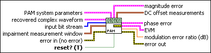
This polymorphic instance calculates
and reports PAM quadrature impairments on a symbol-by-symbol basis at the symbol timing.
|
recovered complex waveform specifies the time-aligned and oversampled complex waveform
data after matched filtering, frequency offset correction, and phase offset
correction. Wire the recovered complex waveform
parameter of the MT Demodulate PAM VI to this parameter.
|
t0 specifies the trigger (start) time of the Y array. The default is 0.0.
|
|
dt specifies the time interval between data points in the Y array. The default is 1.0.
|
|
Y specifies the complex-valued signal-only baseband modulated
waveform. The real and imaginary parts of this complex data array correspond to
the in-phase (I) and quadrature-phase (Q) data, respectively.
|
|
|
input bit stream specifies the demodulated bit stream from the output bit stream parameter of the MT Demodulate PAM VI.
|
|
impairment measurement window specifies the window over which impairments are measured.
|
start index specifies the index of the first sample of the measurement
window. The default is 0.
|
|
width specifies the number of symbols over which to measure
impairments. A value of -1 (default) measures
impairments over all symbols. Positive values must be two or greater.
|
|
|
PAM system parameters specifies parameter values defining the PAM system. Wire the
PAM system parameters cluster returned by either the PAM (M) or PAM (Map) instance of the MT Generate System Parameters VI to this cluster.
|
samples per symbol specifies an even, positive number of samples dedicated to
each symbol. Multiply this value by the symbol rate to determine the sample
rate. The default is 16.
|
|
symbol map specifies an ordered array that maps each Boolean symbol to its
desired coordinates in the complex plane. The number of states in the array must
be 2N, where N is the number of bits per symbol.
|
|
|
reset? specifies how the VI handles bits from partial symbols in the
input bit stream. When reset? is set to TRUE, bits making up incomplete symbols are
discarded. When reset? is set to FALSE, the VI
saves the leftover bits and starts with them on the next iteration. The default is TRUE.
|
|
error in (no error) can accept error information wired from
previously called VIs. Use this information to decide if any functionality
should be bypassed in the event of errors from other VIs. Right-click the front
panel error in control and select Explain Error or Explain
Warning from the shortcut menu for more information about the error.
|
status is TRUE (X) if an error occurred or FALSE (checkmark) to
indicate a warning or that no error occurred. Right-click the front panel
error in control and select Explain Error or Explain
Warning from the shortcut menu for more information about the
error.
|
|
code identifies the error or warning code. Right-click the front
panel error in control and select Explain Error or Explain
Warning from the shortcut menu for more information about the
error.
|
|
source describes the origin of the error or warning. Right-click the
front panel error in control and select Explain Error or Explain
Warning from the shortcut menu for more information about the
error.
|
|
|
phase error returns the measured phase error in degrees. Notice that the phase offset is removed by the
demodulator and is excluded from this measurement.
|
RMS measurement returns the rms impairment value calculated over the
impairment measurement window.
|
|
peak measurement returns the peak impairment value measured over the
impairment measurement window.
|
|
peak symbol index returns the index of the symbol having the peak magnitude of
impairment.
|
|
individual symbol measurements returns the impairment value for each individual symbol.
|
|
|
EVM returns the measured error
vector magnitude (EVM) expressed as a percentage.
|
RMS measurement returns the rms impairment value calculated over the
impairment measurement window.
|
|
peak measurement returns the peak impairment value measured over the
impairment measurement window.
|
|
peak symbol index returns the index of the symbol having the peak magnitude of
impairment.
|
|
individual symbol measurements returns the impairment value for each individual symbol.
|
|
|
modulation error ratio returns the measured modulation error ratio in dB.
|
|
magnitude error returns the measured magnitude error as a percentage of full
scale. Magnitude error is the magnitude difference between the ideal and the
actual measured symbol locations.
|
RMS measurement returns the rms impairment value calculated over the
impairment measurement window.
|
|
peak measurement returns the peak impairment value measured over the
impairment measurement window.
|
|
peak symbol index returns the index of the symbol having the peak magnitude of
impairment.
|
|
individual symbol measurements returns the impairment value for each individual symbol.
|
|
|
DC offset measurements returns the measured DC offset of the I or Q waveforms as a percentage of the largest I and Q value in the symbol map
of the recovered complex waveform.
|
I returns the DC offset of the I waveform, expressed as a
percentage of the largest I or Q value in the symbol map.
|
|
Q returns the DC offset of the Q waveform, expressed as a
percentage of the largest I or Q value in the symbol map.
|
|
origin offset returns the offset, in dB, of the constellation origin from its
ideal location.
|
|
|
error out passes error or warning information out of a VI to be used by
other VIs. Right-click the front panel error out indicator and select
Explain Error or Explain
Warning from the shortcut menu for more information about the
error.
|
status is TRUE (X) if an error occurred or FALSE (checkmark) to
indicate a warning or that no error occurred. Right-click the front panel
error out indicator and select Explain Error or Explain
Warning from the shortcut menu for more information about the
error.
|
|
code is the error or warning code. Right-click the front panel
error out indicator and select Explain Error or Explain
Warning from the shortcut menu for more information about the
error.
|
|
source describes the origin of the error or warning. Right-click the
front panel error out indicator and select Explain Error or Explain
Warning from the shortcut menu for more information about the
error.
|
|
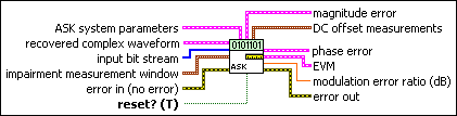
This polymorphic instance calculates
and reports ASK quadrature impairments on a symbol-by-symbol basis at the symbol timing.
|
recovered complex waveform specifies the time-aligned and oversampled complex waveform
data after matched filtering, frequency offset correction, and phase offset
correction. Wire the output complex waveform parameter
of the MT Demodulate ASK VI to this parameter.
|
t0 specifies the trigger (start) time of the Y array. The default is 0.0.
|
|
dt specifies the time interval between data points in the Y array. The default is 1.0.
|
|
Y specifies the complex-valued signal-only baseband modulated
waveform. The real and imaginary parts of this complex data array correspond to
the in-phase (I) and quadrature-phase (Q) data, respectively.
|
|
|
input bit stream specifies the demodulated bit stream from the output bit stream parameter of the MT Demodulate ASK VI.
|
|
impairment measurement window specifies the window over which impairments are measured.
|
start index specifies the index of the first sample of the measurement
window. The default is 0.
|
|
width specifies the number of symbols over which to measure
impairments. A value of -1 (default) measures
impairments over all symbols. Positive values must be two or greater.
|
|
|
ASK system parameters specifies parameter values defining the ASK system. Wire the
ASK system parameters cluster returned by the ASK instance of the MT Generate System Parameters VI to this cluster. Do not
alter the values.
|
samples per symbol specifies an even, positive number of samples dedicated to
each symbol. Multiply this value by the symbol rate to determine the sample
rate. The default is 16.
|
|
symbol map specifies an ordered array that maps each symbol to its desired
level. The number of ASK levels in the array is 2N, where N
is the number of bits per symbol. The length of the vector for the symbols
farthest from the origin is 1.
|
|
|
reset? specifies how the VI handles bits from partial symbols in the
input bit stream. When reset? is set to TRUE, bits making up incomplete symbols are
discarded. When reset? is set to FALSE, the VI
saves the leftover bits and starts with them on the next iteration. The default is TRUE.
|
|
error in (no error) can accept error information wired from
previously called VIs. Use this information to decide if any functionality
should be bypassed in the event of errors from other VIs. Right-click the front
panel error in control and select Explain Error or Explain
Warning from the shortcut menu for more information about the error.
|
status is TRUE (X) if an error occurred or FALSE (checkmark) to
indicate a warning or that no error occurred. Right-click the front panel
error in control and select Explain Error or Explain
Warning from the shortcut menu for more information about the
error.
|
|
code identifies the error or warning code. Right-click the front
panel error in control and select Explain Error or Explain
Warning from the shortcut menu for more information about the
error.
|
|
source describes the origin of the error or warning. Right-click the
front panel error in control and select Explain Error or Explain
Warning from the shortcut menu for more information about the
error.
|
|
|
phase error returns the measured phase error in degrees. Notice that the phase offset is removed by the
demodulator and is excluded from this measurement.
|
RMS measurement returns the rms impairment value calculated over the
impairment measurement window.
|
|
peak measurement returns the peak impairment value measured over the
impairment measurement window.
|
|
peak symbol index returns the index of the symbol having the peak magnitude of
impairment.
|
|
individual symbol measurements returns the impairment value for each individual symbol.
|
|
|
EVM returns the measured error
vector magnitude (EVM) expressed as a percentage.
|
RMS measurement returns the rms impairment value calculated over the
impairment measurement window.
|
|
peak measurement returns the peak impairment value measured over the
impairment measurement window.
|
|
peak symbol index returns the index of the symbol having the peak magnitude of
impairment.
|
|
individual symbol measurements returns the impairment value for each individual symbol.
|
|
|
modulation error ratio returns the measured modulation error ratio in dB.
|
|
magnitude error returns the measured magnitude error as a percentage of full
scale. Magnitude error is the magnitude difference between the ideal and the
actual measured symbol locations.
|
RMS measurement returns the rms impairment value calculated over the
impairment measurement window.
|
|
peak measurement returns the peak impairment value measured over the
impairment measurement window.
|
|
peak symbol index returns the index of the symbol having the peak magnitude of
impairment.
|
|
individual symbol measurements returns the impairment value for each individual symbol.
|
|
|
DC offset measurements returns the measured DC offset of the I or Q waveforms as a percentage of the largest I and Q value in the symbol map
of the recovered complex waveform.
|
I returns the DC offset of the I waveform, expressed as a
percentage of the largest I or Q value in the symbol map.
|
|
Q returns the DC offset of the Q waveform, expressed as a
percentage of the largest I or Q value in the symbol map.
|
|
origin offset returns the offset, in dB, of the constellation origin from its
ideal location.
|
|
|
error out passes error or warning information out of a VI to be used by
other VIs. Right-click the front panel error out indicator and select
Explain Error or Explain
Warning from the shortcut menu for more information about the
error.
|
status is TRUE (X) if an error occurred or FALSE (checkmark) to
indicate a warning or that no error occurred. Right-click the front panel
error out indicator and select Explain Error or Explain
Warning from the shortcut menu for more information about the
error.
|
|
code is the error or warning code. Right-click the front panel
error out indicator and select Explain Error or Explain
Warning from the shortcut menu for more information about the
error.
|
|
source describes the origin of the error or warning. Right-click the
front panel error out indicator and select Explain Error or Explain
Warning from the shortcut menu for more information about the
error.
|
|
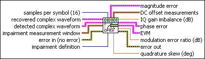
Measures and reports quadrature impairments over a single user-specified window. This VI must be called once for each measurement window. This polymorphic instance calculates CPM quadrature impairments on a point-by-point basis on the oversampled waveform.
|
recovered complex waveform specifies the time-aligned and oversampled complex waveform
data after matched filtering, frequency offset correction, and phase offset
correction. Wire the recovered complex waveform parameter of the MT Demodulate CPM VI to
this parameter.
|
t0 specifies the trigger (start) time of the Y array. The default is 0.0.
|
|
dt specifies the time interval between data points in the Y array. The default is 1.0.
|
|
Y specifies the complex-valued signal-only baseband modulated
waveform. The real and imaginary parts of this complex data array correspond to
the in-phase (I) and quadrature-phase (Q) data, respectively.
|
|
|
detected complex waveform specifies the ideal oversampled waveform. Wire the
detected complex waveform parameter of the MT Demodulate CPM VI to this parameter.
|
t0 specifies the trigger (start) time of the Y array. The default is 0.0.
|
|
dt specifies the time interval between data points in the Y array. The default is 1.0.
|
|
Y specifies the complex-valued signal-only baseband modulated
waveform. The real and imaginary parts of this complex data array correspond to
the in-phase (I) and quadrature-phase (Q) data, respectively.
|
|
|
impairment measurement window specifies the window over which impairments are measured.
|
start index specifies the index of the first sample of the measurement
window. The default is 0.
|
|
width specifies the number of symbols over which to measure
impairments. A value of -1 (default) measures
impairments over all symbols. Positive values must be two or greater.
|
|
|
samples per symbol specifies the number of samples per symbol in the modulated complex waveform. The default is 16.
|
|
impairment definition specifies which set of equations is used to represent impairments.
In the equations in the following table,
I is the real component and Q
is the imaginary component of each sample in the input complex waveform.
I' and Q' are the real and imaginary components
of the corresponding sample in the output complex waveform,
I
° is I DC Offset (%) / 100,
and Q
° is Q DC Offset (%) / 100.
| Vertical Shear (0) |
The definition uses the following equations for I/Q impairments:
I' = a * I + I
°
Q' = a * sin(φ) * I + b * cos(φ) * Q + Q
°
where
φ = the specified quadrature skew, in radians
= 10(IQ gain imbalance/20)
a = * b
b =
In matrix form, these equations are represented by
where
|
| Axis Shear (1) |
With this option selected, this VI uses an impairment definition that simplifies the conversion between measured impairments and their inverse impairments. For example, you may want to measure the I/Q impairments of a system and compensate for those impairments by applying the inverse impairments to the generated or received waveform. Using the Axis Shear definition, given a measured skew and imbalance (in dB), the inverse impairments are –1.0 * skew and –1.0 * imbalance. This definition uses the following equations for IQ impairments:
where
= 10(IQ gain imbalance/20)
φ = the specified quadrature skew, in radians
In matrix form, these equations are represented by
where
|
|
|
error in (no error) can accept error information wired from
previously called VIs. Use this information to decide if any functionality
should be bypassed in the event of errors from other VIs. Right-click the front
panel error in control and select Explain Error or Explain
Warning from the shortcut menu for more information about the error.
|
status is TRUE (X) if an error occurred or FALSE (checkmark) to
indicate a warning or that no error occurred. Right-click the front panel
error in control and select Explain Error or Explain
Warning from the shortcut menu for more information about the
error.
|
|
code identifies the error or warning code. Right-click the front
panel error in control and select Explain Error or Explain
Warning from the shortcut menu for more information about the
error.
|
|
source describes the origin of the error or warning. Right-click the
front panel error in control and select Explain Error or Explain
Warning from the shortcut menu for more information about the
error.
|
|
|
IQ gain imbalance returns the measured ratio of I gain to Q gain, in dB.
|
|
phase error returns the measured phase error in degrees. Notice that the phase offset is removed by the
demodulator and is excluded from this measurement.
|
RMS measurement returns the rms impairment value calculated over the
impairment measurement window.
|
|
peak measurement returns the peak impairment value measured over the
impairment measurement window.
|
|
peak symbol index returns the index of the symbol having the peak magnitude of
impairment.
|
|
individual symbol measurements returns the impairment value for each individual symbol.
|
|
|
EVM returns the measured error
vector magnitude (EVM) expressed as a percentage.
|
RMS measurement returns the rms impairment value calculated over the
impairment measurement window.
|
|
peak measurement returns the peak impairment value measured over the
impairment measurement window.
|
|
peak symbol index returns the index of the symbol having the peak magnitude of
impairment.
|
|
individual symbol measurements returns the impairment value for each individual symbol.
|
|
|
modulation error ratio returns the measured modulation error ratio in dB.
|
|
magnitude error returns the measured magnitude error as a percentage of full
scale. Magnitude error is the magnitude difference between the ideal and the
actual measured symbol locations.
|
RMS measurement returns the rms impairment value calculated over the
impairment measurement window.
|
|
peak measurement returns the peak impairment value measured over the
impairment measurement window.
|
|
peak symbol index returns the index of the symbol having the peak magnitude of
impairment.
|
|
individual symbol measurements returns the impairment value for each individual symbol.
|
|
|
DC offset measurements returns the measured DC offset of the I or Q waveforms as a percentage of the largest I and Q value in the symbol map
of the recovered complex waveform.
|
I returns the DC offset of the I waveform, expressed as a
percentage of the largest I or Q value in the symbol map.
|
|
Q returns the DC offset of the Q waveform, expressed as a
percentage of the largest I or Q value in the symbol map.
|
|
origin offset returns the offset, in dB, of the constellation origin from its
ideal location.
|
|
|
quadrature skew returns the measured quadrature skew of the complex waveform in degrees.
|
|
error out passes error or warning information out of a VI to be used by
other VIs. Right-click the front panel error out indicator and select
Explain Error or Explain
Warning from the shortcut menu for more information about the
error.
|
status is TRUE (X) if an error occurred or FALSE (checkmark) to
indicate a warning or that no error occurred. Right-click the front panel
error out indicator and select Explain Error or Explain
Warning from the shortcut menu for more information about the
error.
|
|
code is the error or warning code. Right-click the front panel
error out indicator and select Explain Error or Explain
Warning from the shortcut menu for more information about the
error.
|
|
source describes the origin of the error or warning. Right-click the
front panel error out indicator and select Explain Error or Explain
Warning from the shortcut menu for more information about the
error.
|
|
For more information about the Vertical Shear definition, refer to Kafadar, Karen. “Statistical Calibration of a Vector Demodulator,” HP Journal: June 1988.