MT Generate System Parameters VI
From LabView Digital Modulation
MT Generate System Parameters VI
Calculates parameters for use with modulation and demodulation VIs. The system parameters cluster from this VI wires to the corresponding parameter of the appropriate demodulation or modulation VI.
Use the pull-down menu to select an instance of this VI.
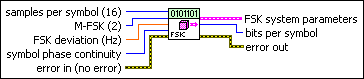
MT Generate FSK System Parameters (M)
This polymorphic instance calculates parameters for use with either the MT Modulate FSK VI or the MT Demodulate FSK VI. This instance accepts an M-ary value that specifies a predefined symbol map with the number of distinct symbol map values to use as symbols.
|
samples per symbol specifies an even, positive number of samples dedicated to each symbol. Multiply this value by the symbol rate to determine the sample rate. The default is 16. |
|||||||
|
M-FSK specifies the M-ary number, which is the number of distinct frequency deviations to use as symbols. This value must be a positive power of 2. The default is 2. |
|||||||
|
FSK deviation specifies the maximum FSK frequency deviation. At baseband frequencies, deviations for individual symbols are evenly spaced in the interval [–f d, f d], where f d represents the frequency deviation. The default is 15,000. |
|||||||
|
symbol phase continuity specifies whether the phase transitions between symbols are continuous. With discontinuous phase-FSK (DPFSK), modulation consists of selecting the appropriate sinusoid based on the input data. Thus when switching between symbols, there is a discontinuity in the FSK signal phase. To emulate a hardware-based DPFSK source, this VI maintains the phase of each independent sinusoid versus time. In this way, the DPFSK modulator acts like a hardware-based (multiple switched tone generator) FSK modulator.
|
|||||||
|
error in (no error) can accept error information wired from previously called VIs. Use this information to decide if any functionality should be bypassed in the event of errors from other VIs. Right-click the front panel error in control and select Explain Error or Explain Warning from the shortcut menu for more information about the error.
|
|||||||
|
FSK system parameters returns parameter values defining the FSK system. Wire this cluster to the corresponding system parameters cluster of the MT Modulate FSK VI or the MT Demodulate FSK VI.
|
|||||||
|
bits per symbol returns the number of bits represented by each symbol. This value is equal to Log2(M), where M is the order of the modulation (for example, for 16-FSK, M=16). |
|||||||
|
error out passes error or warning information out of a VI to be used by other VIs. Right-click the front panel error out indicator and select Explain Error or Explain Warning from the shortcut menu for more information about the error.
|
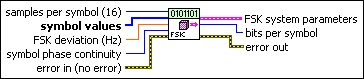
MT Generate FSK System Parameters(map)
This polymorphic instance calculates parameters for use with either the MT Modulate FSK VI or the MT Demodulate FSK VI. This VI accepts an input array of symbol values that explicitly define the positions of the symbol map.
|
samples per symbol specifies an even, positive number of samples dedicated to each symbol. Multiply this value by the symbol rate to determine the sample rate. The default is 16. |
|||||||
|
symbol values specifies an array of symbol values with an order that corresponds to the symbol map. The number of FSK levels specified here must be 2N, where N is the number of bits per symbol. This VI expects an array of integers for the symbol values parameter. The integers 0 through (M-1) must all be included only once in the symbol values array, where M is the M-ary number of the modulation. The symbol locations (FSK frequencies) are evenly spaced between –FSK Deviation and +FSK Deviation, inclusive, with the binary representation (LSB first convention) of the integers that populate the symbol values array that corresponds to the placement of the M-ary bits on the I/Q constellation. For example, for 4-FSK, if you specify FSK deviation as 150k and symbol values as [0 1 3 2], then:
Therefore the generated FSK symbol map reads [–150k –50k 150k 50k]. Similarly, if you specify the symbol values array as [0 1 2 3], the generated FSK symbol map reads [–150k –50k 50k 150k]. |
|||||||
|
FSK deviation specifies the maximum FSK frequency deviation. At baseband frequencies, deviations for individual symbols are evenly spaced in the interval [–f d, f d], where f d represents the frequency deviation. The default is 15,000. |
|||||||
|
symbol phase continuity specifies whether the phase transitions between symbols are continuous. With discontinuous phase-FSK (DPFSK), modulation consists of selecting the appropriate sinusoid based on the input data. Thus when switching between symbols, there is a discontinuity in the FSK signal phase. To emulate a hardware-based DPFSK source, this VI maintains the phase of each independent sinusoid versus time. In this way, the DPFSK modulator acts like a hardware-based (multiple switched tone generator) FSK modulator.
|
|||||||
|
error in (no error) can accept error information wired from previously called VIs. Use this information to decide if any functionality should be bypassed in the event of errors from other VIs. Right-click the front panel error in control and select Explain Error or Explain Warning from the shortcut menu for more information about the error.
|
|||||||
|
FSK system parameters returns parameter values defining the FSK system. Wire this cluster to the corresponding system parameters cluster of the MT Modulate FSK VI or the MT Demodulate FSK VI.
|
|||||||
|
bits per symbol returns the number of bits represented by each symbol. This value is equal to Log2(M), where M is the order of the modulation (for example, for 16-FSK, M=16). |
|||||||
|
error out passes error or warning information out of a VI to be used by other VIs. Right-click the front panel error out indicator and select Explain Error or Explain Warning from the shortcut menu for more information about the error.
|
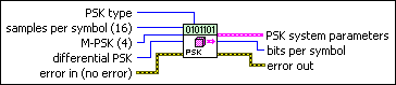
MT Generate PSK System Parameters(M)
This polymorphic instance calculates parameters for use with either the MT Modulate PSK VI or the MT Demodulate PSK VI. This VI generates the symbol map for PSK-modulated systems. It accepts an M-ary value that specifies a predefined symbol map with the number of distinct symbol map values to use as symbols.
Example Symbol Map for PSK
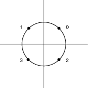
This symbol map corresponds to input symbol values {0, 1, 3, 2} for a quadrature-phase-shift-keying (QPSK) modulation system.
|
samples per symbol specifies an even, positive number of samples dedicated to each symbol. Multiply this value by the symbol rate to determine the sample rate. The default is 16. |
|||||||||
|
M-PSK specifies the M-ary number, which is the number of distinct states that represent symbols in the complex baseband modulated waveform. This value must be a positive power of 2. The default is 4. |
|||||||||
|
differential PSK specifies how the PSK modulation represents symbols. Differential
operation is used to implement PSK formats such as differential quadrature PSK
(DQPSK) and
|
|||||||||
|
PSK type specifies the type of PSK modulation.
|
|||||||||
|
error in (no error) can accept error information wired from previously called VIs. Use this information to decide if any functionality should be bypassed in the event of errors from other VIs. Right-click the front panel error in control and select Explain Error or Explain Warning from the shortcut menu for more information about the error.
|
|||||||||
|
PSK system parameters returns parameter values defining the PSK system. Wire this cluster to the corresponding system parameters cluster of the MT Modulate PSK VI or the MT Demodulate PSK VI.
|
|||||||||
|
bits per symbol returns the number of bits represented by each symbol. This value is equal to Log2(M), where M is the order of the modulation (for example, for 16-PSK, M=16). |
|||||||||
|
error out passes error or warning information out of a VI to be used by other VIs. Right-click the front panel error out indicator and select Explain Error or Explain Warning from the shortcut menu for more information about the error.
|
MT Generate PSK System Parameters(map)
This polymorphic instance calculates parameters for use with either the MT Modulate PSK VI or the MT Demodulate PSK VI. This VI generates the symbol map for PSK-modulated systems. It accepts an array of symbol values that explicitly specifies the positions of the symbol map.
Example Symbol Map for PSK
This symbol map corresponds to input symbol values {0, 1, 3, 2} for a quadrature-phase-shift-keying (QPSK) modulation system.
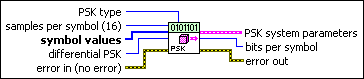
|
samples per symbol specifies an even, positive number of samples dedicated to each symbol. Multiply this value by the symbol rate to determine the sample rate. The default is 16. |
|||||||||
|
symbol values specifies an array of symbol values with an order that corresponds to the symbol map. The number of PSK states in the array must be 2N, where N is the number of bits per symbol. This VI expects an array of integers for the symbol values parameter. The integers 0 through (M–1) must all be included only once in the symbol values array, where M is the M-ary number of the modulation. The binary representation (LSB first convention) of the integers represents the bit pattern that is mapped to the corresponding symbol location in the symbol values array. The symbol locations are generated with equal angles between all M-ary symbol locations and a distance of unity from the origin. For example, in 8-PSK, if you specify symbol values as [5 4 2 7 3 0 1 6], the generated PSK symbol map is [(–0.383 – 0.924i), (0.383 – 0.924i), (–0.383 + 0.924i), (–0.924 – 0.383i), (0.383 + 0.924i), (0.924 + 0.383i), (0.924 – 0.383i), (–0.924 + 0.383i)]. |
|||||||||
|
differential PSK specifies how the PSK modulation represents symbols. Differential
operation is used to implement PSK formats such as differential quadrature PSK
(DQPSK) and
|
|||||||||
|
PSK type specifies the type of PSK modulation.
|
|||||||||
|
error in (no error) can accept error information wired from previously called VIs. Use this information to decide if any functionality should be bypassed in the event of errors from other VIs. Right-click the front panel error in control and select Explain Error or Explain Warning from the shortcut menu for more information about the error.
|
|||||||||
|
PSK system parameters returns parameter values defining the PSK system. Wire this cluster to the corresponding system parameters cluster of the MT Modulate PSK VI or the MT Demodulate PSK VI.
|
|||||||||
|
bits per symbol returns the number of bits represented by each symbol. This value is equal to Log2(M), where M is the order of the modulation (for example, for 16-PSK, M=16). |
|||||||||
|
error out passes error or warning information out of a VI to be used by other VIs. Right-click the front panel error out indicator and select Explain Error or Explain Warning from the shortcut menu for more information about the error.
|
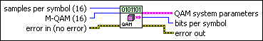
MT Generate QAM System Parameters(M)
This polymorphic instance calculates parameters for use with either the MT Modulate QAM VI or the MT Demodulate QAM VI. It accepts an M-ary value that specifies a predefined symbol map with the number of distinct symbol map values to use as symbols.
|
samples per symbol specifies an even, positive number of samples dedicated to each symbol. Multiply this value by the symbol rate to determine the sample rate. The default is 16. |
|||||||
|
M-QAM specifies the M-ary number, which is the number of distinct states that represent symbols in the complex baseband modulated waveform. This value must be a positive power of 2 and must be less than 256. The default is 16. |
|||||||
|
error in (no error) can accept error information wired from previously called VIs. Use this information to decide if any functionality should be bypassed in the event of errors from other VIs. Right-click the front panel error in control and select Explain Error or Explain Warning from the shortcut menu for more information about the error.
|
|||||||
|
QAM system parameters returns parameter values defining the QAM system. Wire this cluster to the corresponding system parameters cluster of the MT Modulate QAM VI or MT Demodulate QAM VI.
|
|||||||
|
bits per symbol returns the number of bits represented by each symbol. This value is equal to Log2(M), where M is the order of the modulation (for example, for 16-QAM, M=16). |
|||||||
|
error out passes error or warning information out of a VI to be used by other VIs. Right-click the front panel error out indicator and select Explain Error or Explain Warning from the shortcut menu for more information about the error.
|
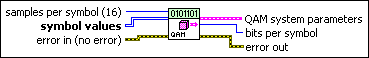
MT Generate QAM System Parameters(map)
This polymorphic instance calculates parameters for use with either the MT Modulate QAM VI or the MT Demodulate QAM VI. It accepts an input array of symbol values that explicitly specifies the positions of the symbol map.
|
samples per symbol specifies an even, positive number of samples dedicated to each symbol. Multiply this value by the symbol rate to determine the sample rate. The default is 16. |
|||||||
|
symbol values specifies an array of symbol values with an order that corresponds to the symbol map. The number of QAM states in the array must be 2N, where N is the number of bits per symbol. The length, or magnitude, of the vector for the symbols farthest from the origin must be 1. This VI expects a two-dimensional, square array of integers for the symbol values parameter. 4-QAM expects a 2×2 array (2 rows, 2 columns), 16-QAM expects a 4×4 array, and so on. The integers 0 through (M–1) must all be included only once in the symbol values array, where M is the M-ary number of the modulation. M must be less than 256. The binary representation (LSB first convention) of the integers represents the bit pattern that is mapped to the corresponding symbol location in the symbol values array. For example, for 4-QAM, if you specify symbol values as
the generated QAM symbol map is [(–0.707 – 0.707i), (0.707 + 0.707i), (0.707 – 0.707i), (–0.707 + 0.707i)]. |
|||||||
|
error in (no error) can accept error information wired from previously called VIs. Use this information to decide if any functionality should be bypassed in the event of errors from other VIs. Right-click the front panel error in control and select Explain Error or Explain Warning from the shortcut menu for more information about the error.
|
|||||||
|
QAM system parameters returns parameter values defining the QAM system. Wire this cluster to the corresponding system parameters cluster of the MT Modulate QAM VI or MT Demodulate QAM VI.
|
|||||||
|
bits per symbol returns the number of bits represented by each symbol. This value is equal to Log2(M), where M is the order of the modulation (for example, for 16-QAM, M=16). |
|||||||
|
error out passes error or warning information out of a VI to be used by other VIs. Right-click the front panel error out indicator and select Explain Error or Explain Warning from the shortcut menu for more information about the error.
|
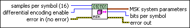
MT Generate MSK System Parameters
This polymorphic instance calculates parameters for use with either the MT Modulate MSK VI or the MT Demodulate MSK VI.
|
samples per symbol specifies an even, positive number of samples dedicated to each symbol. Multiply this value by the symbol rate to determine the sample rate. The default is 16. |
|||||||
|
differential encoding enable specifies whether to enable differential encoding of the bit stream.
|
|||||||
|
error in (no error) can accept error information wired from previously called VIs. Use this information to decide if any functionality should be bypassed in the event of errors from other VIs. Right-click the front panel error in control and select Explain Error or Explain Warning from the shortcut menu for more information about the error.
|
|||||||
|
MSK system parameters returns parameter values defining the MSK system. Wire this parameter to the corresponding system parameters cluster of the MT Modulate MSK VI or the MT Demodulate MSK VI.
|
|||||||
|
bits per symbol returns the number of bits represented by each symbol. This value is equal to Log2(M), where M is the order of the modulation (for example, for 16-MSK, M=16). |
|||||||
|
error out passes error or warning information out of a VI to be used by other VIs. Right-click the front panel error out indicator and select Explain Error or Explain Warning from the shortcut menu for more information about the error.
|
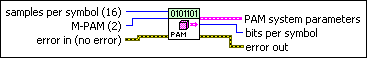
MT Generate PAM system parameters (M)
This polymorphic instance calculates parameters for use with either the MT Modulate PAM VI or the MT Demodulate PAM VI. It accepts an M-ary value that specifies a predefined symbol map with the number of distinct levels to use as symbols.
|
samples per symbol specifies an even, positive number of samples dedicated to each symbol. Multiply this value by the symbol rate to determine the sample rate. The default is 16. |
|||||||
|
M-PAM specifies the M-ary number, which for PAM is the number of distinct states that represent symbols in the complex baseband modulated waveform. This value must be a positive power of 2. The default is 2.
|
|||||||
|
error in (no error) can accept error information wired from previously called VIs. Use this information to decide if any functionality should be bypassed in the event of errors from other VIs. Right-click the front panel error in control and select Explain Error or Explain Warning from the shortcut menu for more information about the error.
|
|||||||
|
PAM system parameters returns parameter values defining the PAM system. Wire this cluster to the corresponding system parameters cluster of the MT Modulate PAM VI or the MT Demodulate PAM VI.
|
|||||||
|
bits per symbol returns the number of bits represented by each symbol. This value is equal to Log2(M), where M is the order of the modulation (for example, for 16-PAM, M=16). |
|||||||
|
error out passes error or warning information out of a VI to be used by other VIs. Right-click the front panel error out indicator and select Explain Error or Explain Warning from the shortcut menu for more information about the error.
|
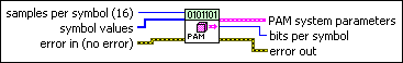
MT Generate PAM system parameters (map)
This polymorphic instance calculates parameters for use with either the MT Modulate PAM VI or the MT Demodulate PAM VI. It accepts an array of symbol values that explicitly specifies the positions of the symbol map with symbols that are evenly distributed between –1 and 1.
|
samples per symbol specifies an even, positive number of samples dedicated to each symbol. Multiply this value by the symbol rate to determine the sample rate. The default is 16. |
|||||||
|
symbol values specifies an array of symbol values with an index-based order that corresponds to the symbol map. The length of the symbol values array must be a positive power of 2, and the entries must be unique and in the range 0 to M-1, where M is the length of the symbol values array. This VI expects an array of integer for the symbol values parameter. The integers 0 through (M-1) must all be included only once in the symbol values array, where M is the M-ary number of the modulation. The binary representation (LSB first convention) of the integers represents the bit pattern that is mapped to the corresponding symbol location in the symbol values array. The symbol locations are evenly spaced between (–1 + 0i) and (1 + 0i), inclusive, along the real axis (I axis). For example, for 4-PAM, if you specify symbol values as [2 3 0 1], the generated PAM symbol map is [(0.333 + 0i), (1 + 0i), (–1 + 0i), (–0.333 + 0i)].
|
|||||||
|
error in (no error) can accept error information wired from previously called VIs. Use this information to decide if any functionality should be bypassed in the event of errors from other VIs. Right-click the front panel error in control and select Explain Error or Explain Warning from the shortcut menu for more information about the error.
|
|||||||
|
PAM system parameters returns parameter values defining the PAM system. Wire this cluster to the corresponding system parameters cluster of the MT Modulate PAM VI or the MT Demodulate PAM VI.
|
|||||||
|
bits per symbol returns the number of bits represented by each symbol. This value is equal to Log2(M), where M is the order of the modulation (for example, for 16-PAM, M=16). |
|||||||
|
error out passes error or warning information out of a VI to be used by other VIs. Right-click the front panel error out indicator and select Explain Error or Explain Warning from the shortcut menu for more information about the error.
|
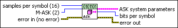
MT Generate ASK system parameters (M)
This polymorphic instance calculates parameters for use with either the MT Modulate ASK VI or the MT Demodulate ASK VI. It accepts an M-ary value that specifies a predefined symbol map with the number of distinct levels to use as symbols.
|
samples per symbol specifies an even, positive number of samples dedicated to each symbol. Multiply this value by the symbol rate to determine the sample rate. The default is 16. |
|||||||
|
M-ASK specifies the M-ary number, which for ASK is the number of distinct states that represent symbols in the complex baseband modulated waveform. This value must be a positive power of 2.
|
|||||||
|
error in (no error) can accept error information wired from previously called VIs. Use this information to decide if any functionality should be bypassed in the event of errors from other VIs. Right-click the front panel error in control and select Explain Error or Explain Warning from the shortcut menu for more information about the error.
|
|||||||
|
ASK system parameters returns parameter values defining the ASK system. Wire this cluster to the corresponding system parameters cluster of the MT Modulate ASK VI or the MT Demodulate ASK VI.
|
|||||||
|
bits per symbol returns the number of bits represented by each symbol. This value is equal to Log2(M), where M is the order of the modulation (for example, for 16-ASK, M=16). |
|||||||
|
error out passes error or warning information out of a VI to be used by other VIs. Right-click the front panel error out indicator and select Explain Error or Explain Warning from the shortcut menu for more information about the error.
|
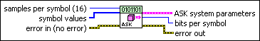
MT Generate ASK system parameters (map)
This polymorphic instance calculates parameters for use with either the MT Modulate ASK VI or the MT Demodulate ASK VI. It accepts an array of symbol values that explicitly specifies the symbol positions of a symbol map with symbols that are evenly distributed between 0 and 1.
|
samples per symbol specifies an even, positive number of samples dedicated to each symbol. Multiply this value by the symbol rate to determine the sample rate. The default is 16. |
|||||||
|
symbol values specifies an array of symbol values with an index-based order that corresponds to the symbol map. The length of the symbol values array must be a positive power of 2, and the entries must be unique and in the range 0 to M-1, where M is the length of the symbol values array. This VI expects an array of integers for the symbol values parameter. The integers 0 through (M-1) must all be included only once in the symbol values array, where M is the M-ary number of the modulation. The binary representation (LSB first convention) of the integers represents the bit pattern that is mapped to the corresponding symbol location in the symbol values array. The symbol locations are evenly spaced between (0 + 0i) and (1 + 0i), inclusive, along the real axis (I axis). For example, for 4-ASK, if you specify symbol values as [2 3 0 1], the generated ASK symbol map is [(0.667 + 0i), (1 + 0i), (0 + 0i), (0.333 + 0i)].
|
|||||||
|
error in (no error) can accept error information wired from previously called VIs. Use this information to decide if any functionality should be bypassed in the event of errors from other VIs. Right-click the front panel error in control and select Explain Error or Explain Warning from the shortcut menu for more information about the error.
|
|||||||
|
ASK system parameters returns parameter values defining the ASK system. Wire this cluster to the corresponding system parameters cluster of the MT Modulate ASK VI or the MT Demodulate ASK VI.
|
|||||||
|
bits per symbol returns the number of bits represented by each symbol. This value is equal to Log2(M), where M is the order of the modulation (for example, for 16-ASK, M=16). |
|||||||
|
error out passes error or warning information out of a VI to be used by other VIs. Right-click the front panel error out indicator and select Explain Error or Explain Warning from the shortcut menu for more information about the error.
|
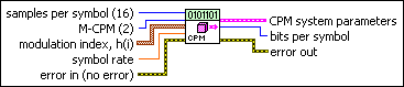
MT Generate CPM System Parameters (M)
This polymorphic instance accepts an M-ary value that specifies a predefined symbol map with the number of distinct symbol map values to use as symbols.
|
samples per symbol specifies the number of samples dedicated to each symbol. Multiply this value by the symbol rate to determine the sample rate. The default is 16. |
|||||||
|
M-CPM specifies the M-ary number, which is the number of distinct frequency deviations to use as symbols. This value must be a positive power of 2. |
|||||||
|
modulation index, h(i) specifies the modulation index for the CPM modulation scheme. Refer to CPM Modulation for more information about modulation indices. The modulation index should be of proper form, that is, the numerator should be lesser than the denominator. The modulation index may vary between symbol intervals.
|
|||||||
|
symbol rate specifies the desired symbol rate, in hertz. |
|||||||
|
error in (no error) can accept error information wired from previously called VIs. Use this information to decide if any functionality should be bypassed in the event of errors from other VIs. Right-click the front panel error in control and select Explain Error or Explain Warning from the shortcut menu for more information about the error.
|
|||||||
|
CPM system parameters returns parameter values defining the CPM system. Wire this control to the corresponding system parameters cluster of the MT Modulate CPM, MT Demodulate CPM, or MT Detect CPM VI.
|
|||||||
|
bits per symbol returns the number of bits represented by each symbol. This value is equal to Log2(M), where M is the order of the modulation (for example, for 4-CPM, M=4). |
|||||||
|
error out passes error or warning information out of a VI to be used by other VIs. Right-click the front panel error out indicator and select Explain Error or Explain Warning from the shortcut menu for more information about the error.
|
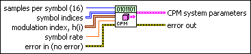
MT Generate CPM System Parameters (Map)
Calculates parameters for use with either the MT Modulate CPM VI or the MT Demodulate CPM VI. Wire the CPM system parameters passed from this VI to the corresponding cluster of the MT Modulate CPM, MT Demodulate CPM, and MT Detect CPM VIs. It accepts an input array of symbol values that explicitly define the positions of the symbol map.
|
samples per symbol specifies the number of samples dedicated to each symbol. Multiply this value by the symbol rate to determine the sample rate. The default is 16. |
|||||||
|
symbol indices specifies an array of symbol values with an order that corresponds to the symbol map. The number of CPM levels specified here must be 2N, where N is the number of bits per symbol. |
|||||||
|
modulation index, h(i) specifies the modulation index for the CPM modulation scheme. Refer to CPM Modulation for more information about modulation indices. The modulation index should be of proper form, that is, the numerator should be lesser than the denominator. The modulation index may vary between symbol intervals.
|
|||||||
|
symbol rate specifies the desired symbol rate, in hertz. |
|||||||
|
error in (no error) can accept error information wired from previously called VIs. Use this information to decide if any functionality should be bypassed in the event of errors from other VIs. Right-click the front panel error in control and select Explain Error or Explain Warning from the shortcut menu for more information about the error.
|
|||||||
|
CPM system parameters returns parameter values defining the CPM system. Wire this control to the corresponding system parameters cluster of the MT Modulate CPM, MT Demodulate CPM, or MT Detect CPM VI.
|
|||||||
|
error out passes error or warning information out of a VI to be used by other VIs. Right-click the front panel error out indicator and select Explain Error or Explain Warning from the shortcut menu for more information about the error.
|