MT Measure Burst Timing VI
Locates a burst within the input complex waveform with peaks correlating to the input ideal power curve.
 |
Note The upper mask, ideal power curve, and lower mask arrays must contain the same number of elements. |

 |
input complex waveform specifies the time-aligned and oversampled complex waveform data after matched filtering and frequency offset correction.
|
||||||
 |
upper mask specifies the upper mask threshold for burst power in dB. The default is 0. |
||||||
 |
ideal power curve specifies the best location for the power curve. This curve is correlated against the input complex waveform to find the peak correlation. The ideal power curve should always be located between the upper mask and the lower mask. The default is 0. |
||||||
 |
lower mask specifies the lower mask threshold for burst power in dB. The default is 0. |
||||||
 |
impairment measurement window specifies—relative to the start of the region delineated by the upper mask, ideal power curve, and lower mask parameters—the portion of the input complex waveform that is measured for amplitude droop and crest factor.
|
||||||
 |
error in (no error) can accept error information wired from previously called VIs. Use this information to decide if any functionality should be bypassed in the event of errors from other VIs. Right-click the front panel error in control and select Explain Error or Explain Warning from the shortcut menu for more information about the error.
|
||||||
 |
pass? returns whether the peak-correlated portion of the input complex waveform meets the upper mask and lower mask specifications. If this parameter is TRUE, all samples fall within the region defined by the upper mask and lower mask parameters. |
||||||
 |
first error sample index returns the index value of the first sample in the peak-correlated portion of the input complex waveform that falls outside of the region defined by the upper mask and lower mask parameters. This index value is an offset into the upper mask/lower mask arrays. |
||||||
 |
correlated burst index returns the index value of the first sample in the peak-correlated portion of the input complex waveform, in samples. This index value is relative to the start of the input complex waveform. |
||||||
 |
crest factor returns the measured crest factor of the power envelope calculated over the specified impairment measurement window. The calculation is defined as the dimensionless quantity [10× log(Max p n)/Mean p n] where p n is the power envelope of the input complex waveform. |
||||||
 |
amplitude droop returns the amplitude droop, in dB, calculated over the specified impairment measurement window. |
||||||
 |
error out passes error or warning information out of a VI to be used by other VIs. Right-click the front panel error out indicator and select Explain Error or Explain Warning from the shortcut menu for more information about the error.
|
Details
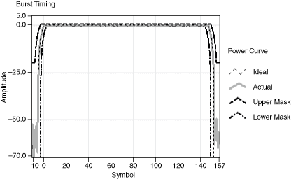
For burst signals, burst timing refers to the location of the burst obtained by its correlation against an ideal power curve. In addition, an upper and lower mask are used to test whether the burst signal satisfies mask specifications. The following figure illustrates the ideal power curve, upper mask, and lower mask.

When located, the VI compares the peak-correlated section with the upper mask and lower mask parameters to validate that the peak-correlated portion falls within the mask specification. Finally, the VI measures and returns the amplitude droop and crest factor of the peak-correlated portion of the input complex waveform.


