| ADC-100 series |


|
From the Settings menu, select Channels....

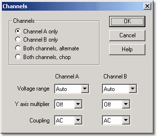
This dialog box enables you to select which input channels to display in the active window and to set the input voltage ranges.
Channels
With an oscilloscope from the ADC-100 series, you can collect data from a single channel, or from a pair of channels. If you want to collect data from more than one channel, there are two modes available: Chop mode and Alternate mode.
Voltage range
oscilloscopes from the ADC-100 series have a number of input voltage ranges. You can either specify an input voltage range, or select Auto, which means the ADC will automatically adjust the voltage range to suit the input signal.
Note: Auto mode does not give good results with trigger signals that occur only once, as PicoScope does not know in advance what range to use.
If you add custom ranges to scale the input from sensors (for example, pressure or acceleration), the custom ranges will appear here and you should select them here if you want to use them.
Y axis multiplier
When a Y multiplier is set at Off, the computer displays the full voltage range over the height of the window.
If you change the Y multiplier to x1, the computer initially displays the full voltage range, but also displays a scroll bar at the left or right of the window. You can use this scroll bar to move the trace up or down, to move it away from other traces.
If you change the Y multiplier to x2 or above, the computer displays only half of the voltage range, but twice as big. The scroll bar now controls which portion of the voltage range is displayed.