Write Motion I/O DataLoads configuration parameters for the motion inputs and outputs.
| Device Compatibility
|
 |
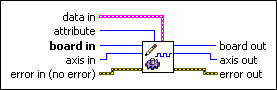
data in is a cluster of variables that contains the values for the selected attribute.
Based on the attribute, the correct member of data in must be set as follows:
|
||||||||||||

|
attribute is the attribute you want to load. The following are valid attributes:
|
||||||||||||
 |
board in is a unique number assigned by Measurement & Automation Explorer used to send and receive commands and data to or from a specific NI motion controller. | ||||||||||||
|
axis in is the axis you are controlling. | ||||||||||||
 |
error in (no error) describes error conditions that occur before this VI runs. The default input of this cluster is no error. If an error already occurred, this VI returns the value of error in in error out. The VI runs normally only if no incoming error exists. Otherwise, the VI passes the error in value to error out. The error in cluster contains the following parameters:
|
||||||||||||
 |
board out is provided for flow control. You can string together NI-Motion VIs by wiring the board out terminal of one VI to the board in terminal of the next VI. | ||||||||||||
|
axis out is provided for flow control. You can string together NI-Motion VIs by wiring the axis out terminal of one VI to the axis in terminal of the next VI. | ||||||||||||
 |
error out contains error information. If error in indicates an error, error out contains the same error information. Otherwise, it describes the error status that this VI produces.
|


Using This VI
Use this VI to load configuration parameters for the motion inputs and outputs on the motion controller. This VI allows you to set all attributes on a per axis basis.
Hardware limit inputs, home inputs, software position limits, inhibit inputs, in-position inputs, drive ready inputs, and inhibit outputs are enhancements on the NI motion controllers and are not required for basic motion control. With the exception of the Find Reference VI, you can operate all motion control VIs without enabling or using these signals. The Find Reference VI requires enabled limit and home inputs for operation. Find Reference does not require enabled software limits.
 |
Caution National Instruments recommends using limits for personal safety, as well as to protect the motion system. |
The active state for each hardware limit, home, inhibit input, in-position input, and inhibit output can be configured as either active low/active open or active high/active closed.
When configured as active low, the input or output is active when there is a low signal on the pin. Conversely, active high means that the input or output is active when there is a high signal on the pin.
Configuring an active state of active open or active closed does not correspond to the level of the signal on the input or output pin. Instead, an active open state means that the input or output is active when current is not flowing through the optocoupled input. Conversely, an active closed state means that the input or output is active when current is flowing through the optocoupled input.
Forward and Reverse Limits, and Home Inputs
The hardware limit inputs are typically connected to end-of-travel limit switches or sensors. An enabled limit input causes a halt stop on the axis when the input becomes active. Active limit inputs also prohibit attempts to start motion that would cause additional travel in the direction of the limit. You also can use limit inputs as general-purpose inputs and read their status with the Read Motion I/O Data VI.
 |
Note For the end-of-travel limits to function correctly, the forward limit switch or sensor must be located at the positive (count up) end of travel and the reverse limit at the negative (count down) end of travel. |
An enabled home input causes a halt stop on the axis when the input becomes active. Refer to Stop Motion for information about halt stop. You also can use a home input as a general-purpose input and read its status with the Read Motion I/O Data VI.
Similar to hardware limits, software limits are often used to restrict the range of travel further and avoid hitting the hardware limit switches. An enabled software limit causes the axis to smoothly decelerate to a stop when the limit position is reached or exceeded. To enable the software limits, you must first find the reference point using the Find Reference VI. The forward software limit is considered active if the current position is greater than or equal to the forward software limit position. The reverse software limit is considered active if the current position is less than or equal to the reverse software limit position.
Software limits are often used to restrict the range of travel and avoid hitting the hardware end-of-travel limit switches. For example, the motor can travel at a high velocity until hitting the software limit switch, and then move more slowly until it hits the hardware limit switch.
|
Note After an axis has stopped when it encounters a software limit switch, you can still move further in the same direction if you command the axis to do so. This behavior is not possible with hardware limits, but is appropriate for software limits. |
|
Note If any axis in a coordinate move exceeds an enabled software limit position, all axes in the coordinate decelerate to a stop. |
Even when disabled, you can poll the software limits with the host computer to warn of an out-of-range position. Refer to the Read Motion I/O Data VI for information about reading the forward and reverse software limit status.
Inhibit Input
Use the inhibit-in input to connect a drive alarm/servo alarm signal to the motion controller so that when an alarm or other drive fault occurs, the motion is stopped using a kill stop. A kill stop asserts inhibit-out, disabling the control loop and zeroing the DAC so that frictional forces stop the motion.
In-Position Input
Use the In-Position drive signal when the drive is closing the position loop, for example a servo drive that accepts p-command or digital signals. This signal tells the motion controller when the drive considers the motor to be at the commanded position.
When the In-Position drive signal is configured, the Move Complete status is linked to the state of the in-position input. The move is not considered complete unless the in-position input is active.
|
Note Refer to Write Trajectory Data to add or remove this signal from the move complete criteria. |
Alarm Clear Output
Use the Alarm Clear Output to pulse the alarm clear signal on one axis of your system. Asserting the Alarm Clear signal clears the drive faults. The output must remain active for a minimum time, which varies depending on your drive. Refer to your drive documentation for more information. Use the alarm clear pulse width attribute to set this time.
Drive Ready Input
The drive ready input can be connected to the drive ready or servo ready output of the drive. The drive ready output is active during normal operation. If the drive ready input signal is inactive, calling Start Motion returns an error. All other VIs can be executed.
 |
Tip Check the status of this input at power-on to verify that the controller is ready to start a move. |
Inhibit Output
When enabled, a per-axis inhibit output is linked to the motor off state of the corresponding axis. A killed axis (motor off) forces the corresponding inhibit output On. When the axis is active, the inhibit output is Off. Note that these On and Off states are logical states. The actual state depends on the polarity of the system.
Inhibit outputs are typically used to disable the servo amplifier or stepper drive for power saving, safety, or specific application reasons.
|
Note Killing a servo axis also zeros its DAC output. With torque block amplifiers, this means that the motor freewheels regardless of if the amplifier is disabled. With velocity block servo amplifiers or stepper drives, the motor does not freewheel unless the amplifier/drive is disabled with the inhibit output. |
You also can use inhibit outputs as general-purpose outputs. Disabled inhibit outputs ignore the state of their corresponding axis and can be directly controlled through the Set Inhibit MOMO VI.
For more information about Open Collector and Totem Pole drive modes, refer to the NI 7350 Hardware User Manual.
Remarks
This section includes information about how the behavior of this VI differs among the controllers that support it.
NI 73xx Controller Considerations
The following list includes considerations you must make when you are using this VI with a 73xx controller:
- 7330, 7340, and 7350 controllers do not support the inhibit-in active state and in-position active state attributes. Use Write Digital I/O Data to set the active state for these signals.
- 7330, 7340, and 7390 controllers do not support the inhibit-out totem pole attribute.
- 7390 controllers do not support the inhibit-out active state attribute. To set the active state on a 7390 use Write Digital I/O Data.
- The inhibit-in signal is software-timed latched at 1 ms. This signal must be active for approximately 1 ms to be detected by the controller.
- The following table lists the drive signals and their implementation on the controller:
Signal Name Signal
DirectionController Support Controller Drive 7330 7340 7350 7390 Inhibit-Out Servo On Output Dedicated Dedicated Dedicated Mappable Inhibit-In Servo Alarm Input Mappable Mappable Mappable Dedicated Drive Ready Servo Ready Input Mappable Mappable Mappable Mappable In-Position In-Position Input Mappable Mappable Mappable Dedicated Alarm Clear Alarm Clear Output Mappable Mappable Mappable Mappable The active state of a dedicated signal is directly configurable using this VI. The active state of a mappable signal is determined by the active state of the line being used.
For example, to set the active state of the Alarm Clear signal, a mappable signal on all controllers, set the active state of the line the signal is mapped to using the Write Digital I/O Data VI.
To set the active state of the inhibit-in signal on a PCI-7390, which has a dedicated line for this signal, use the inhibit-in active state attribute of this VI.
NI SoftMotion Controller Considerations
The following list includes considerations you must make when you are using this VI with the NI SoftMotion Controller:
- NI SoftMotion Controllers do not have to connect the Alarm signal from the drive in order to use the inhibit-in signal.
- The NI SoftMotion Controller does not support the following attributes:
- in-position active state
- pulse alarm clear
- alarm clear pulse width
- drive ready enable
- inhibit-out enable
- inhibit-out totem pole
- inhibit-out active state