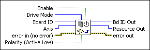
Configure Inhibit OutputsSets polarity and enables the per-axis inhibit outputs.
| Device Compatibility
|
 |
Enable enables/disables inhibit output on the selected axis. | ||||||
 |
Drive Mode specifies either Open Collector (default) or Totem Pole mode. Drive Mode is available only on the NI 7350 and is not configurable on NI 7330/40/90 motion controllers. | ||||||
 |
Board ID is a unique number assigned by Measurement & Automation Explorer (MAX) used to send and receive commands and data to or from a specific NI motion controller. | ||||||
 |
Axis is the axis to configure. | ||||||
 |
error in (no error) describes error conditions that occur before this VI runs. The default input of this cluster is no error. If an error already occurred, this VI returns the value of error in in error out. The VI runs normally only if no incoming error exists. Otherwise, the VI passes the error in value to error out. The error in cluster contains the following parameters:
|
||||||
 |
Polarity sets the polarity for the inhibit output. Select TRUE (default) for active low. Select FALSE for active high. | ||||||
 |
Bd ID Out is provided for flow control. You can string together NI-Motion VIs by wiring the Board ID Out terminal of one VI to the Board ID terminal of the next VI. | ||||||
 |
Resource Out is the Axis, Vector Space, ADC, or Encoder you wired into the VI. Use Resource Out to pass the resource to another VI and/or to display information about the device. | ||||||
 |
error out contains error information. If error in indicates an error, error out contains the same error information. Otherwise, it describes the error status that this VI produces.
|
Using This VI
The Configure Inhibit Outputs VI enables/disables the inhibit outputs, sets the Polarity (active low or active high) of the axis inhibit outputs, and sets the Drive Mode. When enabled, a per-axis inhibit output is linked to the motor off state of the corresponding axis. A killed axis (motor off) forces the corresponding inhibit output On. When the axis is active, the inhibit output is Off. Notice that this is the logical state. The actual state depends on the polarity of the system.
Inhibit outputs are typically used to disable the servo amplifier or stepper drive for power saving, safety, or specific application reasons.
For more information about Open Collector and Totem Pole drive modes, refer to the NI 7350 Hardware User Manual. Configuring Drive Mode is supported only on 7350 controllers and is not configurable on NI 7330/40/90 motion controllers.
 |
Note Killing a servo axis also zeros its DAC output. With torque block amplifiers, this means that the motor freewheels regardless of whether the amplifier is disabled. With velocity block servo amplifiers or stepper drives, the motor does not freewheel unless the amplifier/drive is disabled with the inhibit output. |
You also can use inhibit outputs as general-purpose outputs. Disabled inhibit outputs ignore the state of their corresponding axis and can be directly controlled through the Set Inhibit MOMO VI.
You can configure the polarity of each inhibit output as active low or active high. When configured as active low, the output is active when there is a low signal on the output pin. Conversely, active high means that the output is active when there is a high signal on the output pin. The inhibit polarity is always in effect, whether the inhibit is linked to its axis (enabled) or directly controlled through the Set Inhibit MOMO VI.
Remarks
This section includes information about how the behavior of this VI differs among the controllers that support it.
NI 73xx Controller Considerations
The following includes considerations you must make when you are using this VI with a 73xx motion controller:
The PCI-7390 does not support the Polarity parameter. To set the active state on a PCI-7390 use Write Digital I/O Data.


