Set I/O Port MOMO
From NI-Motion VI
Set I/O Port MOMOSets an I/O port value using the Must On/Must Off protocol.
| Device Compatibility
|
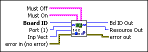
| Must Off is the bitmap of I/O port bits to force off. | |||||||
| Board ID is a unique number assigned by Measurement & Automation Explorer (MAX) used to send and receive commands and data to or from a specific NI motion controller. | |||||||
| Must On is the bitmap of I/O port bits to force on. | |||||||
| Inp Vect indicates the source of the data for this VI. Available input vectors include immediate (0xFF), variable (0x01 through 0x78), or indirect variable (0x81 through 0xF8). Refer to Input and Return Vectors for more detailed information. | |||||||
| Port (1) is the general-purpose I/O port (1–8) or RTSI software port (9) to control. | |||||||
error in (no error) describes error conditions that occur before this VI
runs. The default input of this cluster is no error. If an
error already occurred, this VI returns the value of error in in
error out. The VI runs normally only if no incoming error exists.
Otherwise, the VI passes the error in value to error
out. The error in cluster contains the following parameters:
|
|||||||
| Bd ID Out is provided for flow control. You can string together NI-Motion VIs by wiring the Bd ID Out terminal of one VI to the Board ID terminal of the next VI. | |||||||
| Resource Out is the Axis, Vector Space, ADC, or Encoder you wired into the VI. Use Resource Output to pass the resource to another VI and/or to display information about the device. | |||||||
error out contains error information. If error in
indicates an error, error out contains the same error information.
Otherwise, it describes the error status that this VI produces.
|
Using This VI
The Set I/O Port MOMO VI sets the logical state of bits in the general-purpose I/O port selected.
Using the Must On/Must Off protocol allows you to set or reset individual bits without affecting other output bits in the port. This gives you tri-state control over each bit: on, off or unchanged. A True in a bit location of the Must On bitmap turns the bit on, while a True in the corresponding location of the Must Off bitmap turns the bit off. A False in either bitmap has no effect, so leaving both the Must On and Must Off bits at zero is effectively a hold and the state of the bit is unchanged. If you set both the Must On and Must Off bits to True, it is interpreted as a Must On condition and the bit is turned on.
| Note This VI sets the logical state of a bit On or Off (True or False). The polarity of the bits in the port determines whether an On state is active high or active low. Refer to the Set I/O Port Polarity VI for more information. |
| Note When executing the Set I/O Port MOMO VI in a LabVIEW program, there may be a delay of up to 0.5 ms before the output lines are physically updated. The LabVIEW program flow continues, even though the output may not be updated yet. |
| Note If the motion controller is programmed to use the port for output when it has been configured for input, the action is ignored. |
The Set I/O Port MOMO VI allows individual control of general-purpose output bits without requiring a shadow value or a read of the port to remember the state of other bits not being set or reset with the VI.
Example
| Tip This section applies to all NI motion controllers. |
In I/O port 2, to set bits 1 and 3 On, bits 0 and 5 Off, and to leave the other bits (2, 4, 6, and 7) unchanged, call this VI with the following parameters:
Port = 2
Must On corresponds to the values shown in the following table.
| Must On 0 | Must On 1 | Must On 2 | Must On 3 | Must On 4 | Must On 5 | Must On 6 | Must On 7 |
| False | True | False | True | False | False | False | False |
Must Off corresponds to the values shown in the following table.
| Must On 0 | Must On 1 | Must On 2 | Must On 3 | Must On 4 | Must On 5 | Must On 6 | Must On 7 |
| True | False | False | False | False | True | False | False |
| Note Refer to VI Execution Times for benchmark timing information about your controller. |
Remarks
This section includes information about how the behavior of this VI differs among the controllers that support it.
NI 73xx Controller Considerations
The following list includes considerations you must make when you are using this VI with a 73xx motion controller:
- A line configured for input is not affected by this VI.
- You can always write to the RTSI software port, but the actual RTSI lines on the physical RTSI port are only affected if the RTSI line has been configured properly by using the Select Signal VI. By default, none of the RTSI lines are configured to output their corresponding bits in the RTSI software port; you must configure each RTSI line individually using the Select Signal VI, rather than the Set I/O Port Direction VI.
- The PCI-7390 has dedicated direction I/O ports. Refer to 73xx Controller General-Purpose I/O Port IDs for the appropriate port number to use for Port.
For example, to set the state of output port 2, Port is 0x82 (130). To set the state of input port 3, Port is 0x03 (3).
NI SoftMotion Controller Considerations
The following list includes considerations you must make when you are using this VI with the NI SoftMotion Controller:
- Refer to General-Purpose I/O Ports for information about how the NI SoftMotion Controller supports digital input and output lines for each axis.
- For Inp Vect, the NI SoftMotion Controller supports only the immediate vector (0XFF).
- The NI SoftMotion Controller has dedicated direction I/O ports. Refer to NI SoftMotion Controller General-Purpose I/O Port IDs for the appropriate port number to use for Port.
For example, to set the state of output port 2, Port is 0x82 (130). To set the state of input port 3, Port is 0x03 (3). - The RTSI port is not supported by the NI SoftMotion Controller.