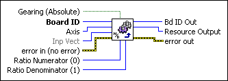
Load Gear RatioLoads the gear ratio for master-slave gearing.
| Device Compatibility
|
 |
Gearing (Absolute) selects absolute FALSE or relative TRUE gearing between the master and slave. | ||||||
 |
Board ID is a unique number assigned by Measurement & Automation Explorer (MAX) used to send and receive commands and data to or from a specific NI motion controller. | ||||||
 |
Axis is the slave axis to control. | ||||||
 |
Inp Vect contains the type, numerator, and denominator parameters that are the source of data for this VI.
Available input vectors include immediate (0xFF), variable (0x01 through 0x78), or indirect variable (0x81 through 0xF8). Refer to Input and Return Vectors for more detailed information. |
||||||
 |
error in (no error) describes error conditions that occur before this VI runs. The default input of this cluster is no error. If an error already occurred, this VI returns the value of error in in error out. The VI runs normally only if no incoming error exists. Otherwise, the VI passes the error in value to error out. The error in cluster contains the following parameters:
|
||||||
 |
Ratio Numerator (0) is the gear ratio numerator of the slave relative to the master. The numerator is a signed value between -32,768 to +32,767 to allow for both positive and negative gearing. | ||||||
 |
Ratio Denominator (1) is the gear ratio denominator of the slave relative to the master. The denominator must be between 1 to 32,767. | ||||||
 |
Bd ID Out is provided for flow control. You can string together NI-Motion VIs by wiring the Bd ID Out terminal of one VI to the Board ID terminal of the next VI. | ||||||
 |
Resource Output is the Axis, Vector Space, ADC, or Encoder you wired into the VI. Use Resource Output to pass the resource to another VI and/or to display information about the device. | ||||||
 |
error out contains error information. If error in indicates an error, error out contains the same error information. Otherwise, it describes the error status that this VI produces.
|
Using This VI
The Load Gear Ratio VI loads the gear ratio of the slave axis relative to its master and selects whether this ratio is absolute or relative. The ratio is loaded as a numerator and denominator because it is a natural format for a ratio (numerator : denominator ) and it allows a broad range of ratios, from 1:32,767 to 32,767:1. The ratio is always specified as slave relative to master (slave:master).
When you execute the Enable Gearing VI, the positions of the slave and its master are recorded as their absolute gearing reference. From then on, as long as the gear ratio remains absolute, every incremental change of the master's position is multiplied by the absolute gear ratio and applied to the slave axis.
If a relative gear ratio is selected and loaded after gearing is enabled, the position of the master is recorded as its relative reference point and every incremental change from this reference point is multiplied by the relative gear ratio and applied to the slave axis or axes.
 |
Note While changing an absolute gear ratio on the fly is allowed, you must be careful because the slave axis jumps with full torque to the position defined by the new ratio even when the master position has not changed. Similarly, resetting the position on a master axis also causes its slave axes to jump to a new position relative to the new position of the master axis. |
The Load Gear Ratio VI must be called prior to enabling master-slave gearing with the Enable Gearing VI. Often the positions of the master and slave are reset to zero or some known position prior to enabling gearing, though this is not always required. The execution of the Enable Gearing VI stores both positions as offsets and gears them from that point onward.
Relative gearing changes the specified position of the slave axis only when the master moves. It uses the length of the current move of the master axis to calculate how far to move the slave axis. At the end of the move, if the slave axis is not at the exact position, the position error is discarded. This may happen when the true target for the slave axis is a fractional position, which is impossible to actually reach. The position error can add up over time to become significant. If it becomes a problem, call this VI with absolute gearing selected to correct for the accumulated error. The controller calculates where the slave is supposed to be relative to the offset of the master axis beginning from the position where gearing was enabled. With gearing ratios less than 1, this problem does not appear.
Master-slave functionality of slave axes is in addition to their normal mode of operation. This allows a point-to-point move to be superimposed upon the slave axis while the slave axis is in motion due to being geared to its master. This functionality is useful for registration and reference offset moves. Refer to the Gearing section of the NI-Motion Help for information about using superimposed moves/registration applications. Also, refer to the Rotating Knife section of the NI-Motion Help for example code that includes superimposed moves.
Refer to the Configure Gear Master and Enable Gearing VIs for more information about master-slave gearing.
Example
To load a slave to master gear absolute gear ratio of 3:2, call the Load Gear Ratio VI with Gearing = 0 (absolute), Ratio Numerator = 3 and Ratio Denominator = 2. For two axes with identical resolution, setting a gear ratio of 3:2 results in the slave axis rotating three revolutions for every two revolutions of the master.


