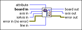
Configure Motion I/O MapMaps a general purpose I/O line to an alternate function of an axis.
| Device Compatibility
|
 |
attribute is the action to map to a digital I/O line. The following are valid attributes:
|
||||||
 |
board in is a unique number assigned by Measurement & Automation Explorer used to send and receive commands and data to or from a specific NI motion controller. | ||||||
 |
axis in is the axis you are controlling. | ||||||
 |
ioAxis in is the axis of the digital I/O line to map. | ||||||
 |
line in is line of ioAxis in to map. | ||||||
 |
error in (no error) describes error conditions that occur before this VI runs. The default input of this cluster is no error. If an error already occurred, this VI returns the value of error in in error out. The VI runs normally only if no incoming error exists. Otherwise, the VI passes the error in value to error out. The error in cluster contains the following parameters:
|
||||||
 |
board out is provided for flow control. You can string together NI-Motion VIs by wiring the board out terminal of one VI to the board in terminal of the next VI. | ||||||
 |
axis out is provided for flow control. You can string together NI-Motion VIs by wiring the axis out terminal of one VI to the axis in terminal of the next VI. | ||||||
 |
error out contains error information. If error in indicates an error, error out contains the same error information. Otherwise, it describes the error status that this VI produces.
|
Using This VI
This VI maps a general-purpose I/O line to an alternate function of an axis such as inhibit output. For example, to map axis 3 general-purpose output 1 to the inhibit output of axis 3, call the VI with the following parameter values:
axis in = 3
attribute = inhibit-out
ioAxis in = 3
line in = 1
 |
Notes
|
The following table lists the drive signals and their implementation on the controller:
| Signal Name | Signal Direction |
Controller Support | ||||
|---|---|---|---|---|---|---|
| Controller | Drive | 7330 | 7340 | 7350 | 7390 | |
| Inhibit-Out | Servo On | Output | Dedicated | Dedicated | Dedicated | Mappable |
| Inhibit-In | Servo Alarm | Input | Mappable | Mappable | Mappable | Dedicated |
| Drive Ready | Servo Ready | Input | Mappable | Mappable | Mappable | Mappable |
| In-Position | In-Position | Input | Mappable | Mappable | Mappable | Dedicated |
| Alarm Clear | Alarm Clear | Output | Mappable | Mappable | Mappable | Mappable |
The active state of a dedicated signal is directly configurable using this VI. The active state of a mappable signal is determined by the active state of the line being used.
For example, to set the active state of the Alarm Clear signal, a mappable signal on all controllers, set the active state of the line the signal is mapped to using the Write Digital I/O Data VI.
To set the active state of the inhibit-in signal on a PCI-7390, which has a dedicated line for this signal, use the inhibit-in active state attribute of the Write Motion I/O Data VI.
You cannot use this function to map signals on NI 7330/7340/7350 controllers on lines greater than line 7. For example, on an NI 7356 controller, you can use this function to configure axis 5, lines 0 through 7 (port 5), but you cannot configure lines 8 through 15, which are on the second port (port 7) of axis five. Refer to the Remarks section of Write Digital I/O Data for the port to axis and line mapping for these controllers.


