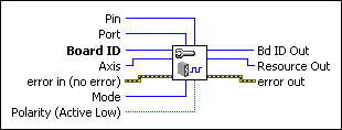
Configure Drive SignalConfigures the drive signal.
|
Device Compatibility
|
 |
Pin is the specific bit (0 to 7) in the port specified by port. For the HSC port, trigger 1 = pin 0, trigger 2 = pin 1, trigger 3 = pin 2, trigger 4 = pin 3, trigger 5 = pin 4, trigger 6 = pin 5, trigger 7 = pin 6, and trigger 8 = pin 7. | ||||||
 |
Port is the general purpose I/O port (1 to 8) or HSC software port (10) to control. | ||||||
 |
Board ID is a unique number assigned by MAX used to send and receive commands and data to or from a specific NI motion controller. | ||||||
 |
Axis is the axis to configure. | ||||||
 |
error in (no error) describes error conditions that occur before this VI runs. The default input of this cluster is no error. If an error already occurred, this VI returns the value of error in in error out. The VI runs normally only if no incoming error exists. Otherwise, the VI passes the error in value to error out. The error in cluster contains the following parameters:
|
||||||
 |
Mode is the mode that pin will be reserved for. Options include Clear All, In-Position, and Drive Fault. If a DIO or high-speed capture line has been reserved for a drive signal, I/O functionality is blocked for the reserved pin. You must use the Read Drive Signal Status VI to read the status of this signal. | ||||||
 |
Polarity sets the polarity for the drive signal. Select TRUE (default) for active low. Select FALSE for active high. | ||||||
 |
Bd ID Out is provided for flow control. You can string together NI-Motion VIs by wiring the Bd ID Out terminal of one VI to the Board ID terminal of the next VI. | ||||||
 |
Resource Out is the Axis, Vector Space, ADC, or Encoder you wired into the VI. Use Resource Output to pass the resource to another VI and/or to display information about the device. | ||||||
 |
error out contains error information. If error in indicates an error, error out contains the same error information. Otherwise, it describes the error status that this VI produces.
|
Using This VI
Use this VI to configure and reserve I/O lines to receive signals from the drive. The following drive signals are available: In-Position and Drive Fault (Servo Alarm).
 |
Tip Use Configure Motion I/O Map instead of this VI for additional drive signal support. |
Use the In-Position drive signal when the drive is controlling a servo motor and the input to the drive is step/direction. This signal tells the motion controller when the drive considers the motor to be at the commanded position.
When the In-Position drive signal is configured, the Move Complete status is linked to the state of the In-Position signal. The move is not considered complete unless the In-Position signal is active.
 |
Note Refer to Write Trajectory Data to add or remove this signal from the move complete criteria. |
Use the Drive Fault drive signal to connect a servo alarm signal to the motion controller so that when an alarm or other drive fault occurs, the motion is stopped using a kill stop. A kill stop disables the control loop and zeroes the DAC so that frictional forces stop the motion.


