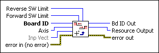
Load Software Limit PositionsLoads the forward and reverse software limit positions for an axis.
| Device Compatibility
|
 |
Reverse SW Limit
is the reverse software limit position in counts (servo axes) or steps (stepper axes). Software limit positions can be anywhere within the 32-bit position range, –(231) to +(231–1). The default value for the reverse software limit is –(230) counts (steps).
|
||||||
 |
Forward SW Limit is the forward software limit position in counts (servo axes) or steps (stepper axes). Software limit positions can be anywhere within the 32-bit position range, –(231) to +(231–1). The default value for the forward software limit is +(230)–1 counts (steps). | ||||||
 |
Board ID is a unique number assigned by Measurement & Automation Explorer (MAX) used to send and receive commands and data to or from a specific NI motion controller. | ||||||
 |
Axis is the axis to control. | ||||||
 |
Inp Vect indicates the source of the data for this VI. Available input vectors include immediate (0xFF), variable (0x01 through 0x78), or indirect variable (0x81 through 0xF8). Refer to Input and Return Vectors for more detailed information. | ||||||
 |
error in (no error) describes error conditions that occur before this VI runs. The default input of this cluster is no error. If an error already occurred, this VI returns the value of error in in error out. The VI runs normally only if no incoming error exists. Otherwise, the VI passes the error in value to error out. The error in cluster contains the following parameters:
|
||||||
 |
Bd ID Out is provided for flow control. You can string together NI-Motion VIs by wiring the Bd ID Out terminal of one VI to the Board ID terminal of the next VI. | ||||||
 |
Resource Output is the Axis, Vector Space, ADC, or Encoder you wired into the VI. Use Resource Output to pass the resource to another VI and/or to display information about the device. | ||||||
 |
error out contains error information. If error in indicates an error, error out contains the same error information. Otherwise, it describes the error status that this VI produces.
|
Using This VI
The Load Software Limit Positions VI sets the forward and reverse position limit values for the selected axis. When enabled with the Enable Limits VI, a software limit causes the axis to smoothly decelerate to a stop when the limit position is reached or exceeded.
Even when disabled, you can poll the software limits by the host computer or use an onboard program to warn of an out of range position. Refer to the Read Limit Status VI for information about reading the software limit status.
The forward software limit is considered active if the current position is greater than or equal to the forward software limit position. The reverse software limit is considered active if the current position is less than or equal to the reverse software limit position.
Software limits are often used to restrict the range of travel and avoid hitting the hardware end-of-travel limit switches. For example, you can travel at a high velocity until hitting the software limit switch, and then move more slowly until hitting the hardware limit switch.
 |
Caution After an axis has stopped due to encountering a software limit switch, you can still move further in the same direction if you command the axis to do so. This behavior is not possible with hardware limits, but is appropriate for software limits. |
 |
Note If you are doing onboard programming and are using Inp Vect to get the data this VI needs, remember that this VI reads the variables starting at the memory address pointed to by Inp Vect in the following order: Forward SW Limit, Reverse SW Limit. |


