Exercise 6: Display the raster image behind other features
From AutoCAD Map 3D 2009
You want the raster image to provide context for the parcels in your map, but right now it is hiding the parcels. Move the raster behind the parcels and set transparency for the parcels so you can see the raster image.
To display the raster image behind other features
- In
the BuildMap1.dwg file,
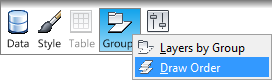
in the Display Manager menu
bar, make sure the fourth item reads Draw Order.
If it reads Groups, click it and change
it to Draw Order.
- Drag
the new raster layer just below the Parcels layer.
The list of layers is the draw order (Z-order) for your map. The item at the top of the list is also at the top of the map’s Z-order. Dragging the raster image below the Parcels layer places it behind that layer in your map.
To see the raster layer behind the parcels, make the city boundary layer white and make the parcels semi-transparent.
- In Display Manager, select the City_Boundary layer.
- Click Style to
see the Style Editor.NoteIf the Style Editor is docked, move your cursor over it to display it. It may be docked at the left side of the application window.
- In the Style Editor, in the Polygon Style For 0 - Infinity: Scale Range section, click the Style entry.
- Change the Foreground Color to white and click OK.
- Without
closing the Style Editor, select the Parcels layer
in Display Manager.
The Data Connect dialog box updates to show the values for the Parcels layer.
- In the Style Editor, click the Style entry again.
- Move
the Foreground Transparency slider
to 50% and click OK.
Close the Style Editor. Right-click the Parcels layer and click Zoom To Extents to see the results.
- Save your map.
You have assembled all the raw materials for your map. The aerial photograph provides context. The geometry from the DWG drawing shows the county boundaries, and the SDF files add the city boundary and parcel outlines.