Onboard Subroutine LabVIEW Diagram
 |
Tip Refer to NI-Motion\Documentation\Examples\NI-Motion User Manual\ for the LabVIEW VIs for these examples. |
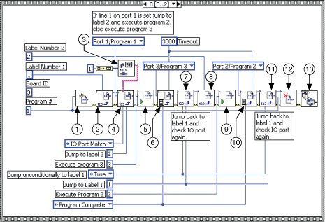
The following figure shows the main onboard program used to determine the subroutine call.
|
||
| 1 Begin Program Storage | 6 Wait on Condition | 10 Wait on Condition |
| 2 Insert Program Label | 7 Jump to Label on Condition | 11 Jump to Label on Condition |
| 3 Select MOMO | 8 Insert Program Label | 12 End Program Storage |
| 4 Jump to Label on Condition | 9 Run Program | 13 Motion Error Handler |
| 5 Run Program | ||
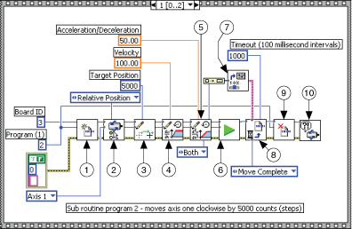
The following figure shows the subroutine that causes the motor to rotate clockwise.
|
||
| 1 Begin Program Storage | 5 Load Accel/Decel in RPS/sec | 8 Wait on Condition |
| 2 Set Operation Mode | 6 Start Motion | 9 End Program Storage |
| 3 Load Target Position | 7 Select MOMO | 10 Motion Error Handler |
| 4 Load Velocity in RPM | ||
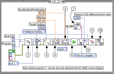
The following figure shows the subroutine that causes the motor to rotate counter clockwise.
|
||
| 1 Begin Program Storage | 5 Load Accel/Decel in RPS/sec | 8 Wait on Condition |
| 2 Set Operation Mode | 6 Start Motion | 9 End Program Storage |
| 3 Load Target Position | 7 Select MOMO | 10 Motion Error Handler |
| 4 Load Velocity in RPM | ||


