Camming Application Example
An example of a motion control system that can benefit from the flexibility of electronic camming is welding parts as they travel on a conveyor belt.
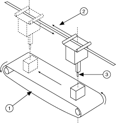
The following figure shows that the welding point moves to the first position, and then welds the material for a couple of seconds. Because the conveyor belt keeps moving at a constant rate, the welding point must follow the material at the same speed as the conveyor belt during the weld process. When the welding process is finished for one item, the welding point must quickly return to its initial position and the process repeats.
|
| 1 Conveyor belt |
| 2 Movement of the welder as it follows the object, and then returns to the initial position |
| 3 Welding point |
In this application, the master device is the position encoder attached to the conveyor belt, and the slave axis is the actuator that moves the welding point. The slave axis repeatedly performs a two-segment movement:
- First, it follows the material with the same speed as the conveyor belt.
- Next, it returns to the initial position as the next material approaches.
Each segment of the move is represented with a gear ratio that dictates how fast and in which direction the welding point is moving relative to the conveyor belt.
This application requires the slave axis to switch from one ratio to the other at the correct master position, otherwise the welding process is not repeatable. If this application used gearing instead of camming, the latency, or delay, of loading a new gear ratio might cause an accumulation of position errors.
When a camming operation is active, the slave axis follows a profile that is established using a list of master and slave positions pairs, called the camming table and is loaded into a buffer for use during a camming operation. An example of a camming table is shown below.
The following figure shows that, in the welding example defined previously, the conveyor belt is moving at 1,000 counts/s and the parts to be welded are 6,000 counts apart. To weld the part, the welding point must follow the part down the conveyor belt for 2 seconds.
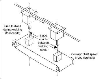
In this welding application, the slave axis must follow the part with the same velocity as the conveyor belt while welding is in progress. Because it takes two seconds to weld each part, the welding point and conveyor belt have both moved 2,000 counts by the time the welding is complete. This part of the welding application creates the first move segment.
For the second move segment, the welding point must return to its original position so that it can weld the next part on the conveyor belt. To move the welding point to its original position at the same time that the next part is in the correct position on the conveyor belt, the welding point must travel 2,000 counts in the opposite direction of the conveyor belt at half the speed that the conveyor belt is traveling at. The following figure shows the move profile of the first and second move segments.
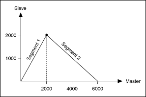
The following table shows the camming table that corresponds to the move profile used in this example.
| Time (seconds) | Master Position (counts) | Slave Position (counts) | Ratio* |
|---|---|---|---|
| 0 | 0 | 0 | |
| 2 | 2000 | 2000 | 1 |
| 4 | 4000 | 1000 | 0.5 |
| 6 | 6000 | 0 | 0.5 |
| * Ratio = ΔSlaveDistance / ΔMasterDistance | |||
The camming cycle is 6,000 counts and is divided into equal length segments.
 |
Tip Because the camming cycle is 6,000 counts, the master cycle must also be 6,000 counts. |
Each row of data defines a gear ratio. The camming profile is repeated after a camming cycle is completed. The master position is always interpreted inside the modulus defined by the camming cycle.
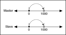 |
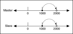
For example, initially, the master axis moves from 0 to 1000. The gear ratio used for this move is 1:1 because the master position is in the 0 to 2000 interval. With a gear ratio of 1:1, the slave axis moves at the same speed as the master device to position 1000.
As shown, the master position in this interval is inside the modulus. |
 |
If the master axis moves to position 2000, the gear ratio does not change because the current master position is still inside the 0 to 2000 interval. |
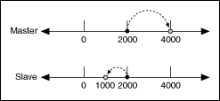 |
When the master axis moves to position 4,000, the gear ratio changes to 0.5. The slave axis travels half the distance that the master axis travels, and it travels in the opposite direction. |
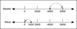 |
When the master reaches position 6000, the slave axis moves back the original position, and the camming cycle begins again. |
