Circular Arcs
A circular arc defines an arc in the XY plane of a 2D or 3D coordinate space. The arc is specified by a radius, starting angle, and travel angle. Also, like all coordinate space moves, the arc uses the values of move constraints—maximum velocity, maximum acceleration, and maximum deceleration.
 |
Tip For the NI SoftMotion Controller, the arc generation also uses acceleration jerk and deceleration jerk while calculating the arc move. |
 |
Note When you use an NI 73xx motion controller to move a motor in an arc, you can use only trapezoidal profiles. You do not use jerk to calculate the profile for arc moves. |
To move axes in a circular arc, the motion controller needs the following information:
- Radius—Specifies the distance from the center of the arc to its edge
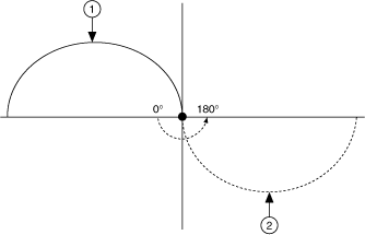
- Start Angle—Orients the arc on its plane using the starting point as an axis to spin around. Because the starting point for a new arc is fixed based on the current position, moving its center around the starting point alters the orientation of a new arc. For example, the following figure shows the effect of changing the start angle from 0° to 180°.

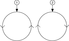
1 Original Arc 2 Arc with 180° Start Angle - Travel Angle—Indicates how far the arc travels in a 360° circle. For example, a travel angle of 90° executes a quarter-circle, a travel angle of 360° creates a full circle, and a travel angle of 720° creates two full circles. A positive travel angle always creates counterclockwise circular motion. A negative travel angle reverses the direction to create clockwise circular motion, as shown in the following figure.

1 Positive Travel Angle 2 Negative Travel Angle
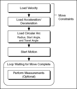
Circular Arc Move Algorithm
The following figure shows a generic circular arc move algorithm applicable to both C/C++ and LabVIEW code.
