This section is applicable to any wireless 802.11 products and describes the client device in an infrastructure network type. The approach remains similar when analyzing other network types.
Wireless sniffer hardware, such as AirPcap USB adaptor by Riverbed Technology, is needed to capture the wireless packets. Here it is assumed the user has knowledge of setting up the wireless sniffer hardware for packets capture.
Software such as Wireshark is needed to analyse the wireless packets captured.
Even if you do not have the hardware and only have the wireshark capture file (with file extension *.pcapng), this software is still needed to view and analyze the wireless packets capture file.
To capture 802.11 wireless packets, a sniffer hardware such as the AirPcap is required. Certain configurations will not allow you to capture 802.11 wireless packets.
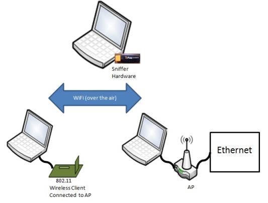
• A laptop/PC that has wireless network capabilities or wireless adaptor with an AP connected to this laptop/PC via wired Ethernet cable is not sufficient as this environment is likely to be in non-promiscuous mode. . This means that many packets will be filtered and not shown on the wireshark trace. If using wired ethernet or the built-in PC NIC, generally only packets meant for the PC are displayed. The AirPcap allows selecting a promiscuous NIC that will display all traffic in the air.
• A laptop/PC that has wireless network capabilities or wireless adaptor and only plugged into wired Ethernet. This will only allow monitoring of Ethernet traffic and specifically traffic that is targeted to the PC, even though this laptop/PC is 802.11 wireless connected to some wireless devices. Also this method will prevent seeing packets that are attempting to make it to the PC or anywhere else but are not getting through due to any misconfigurations.
Below figure shows the recommended configuration for wireless packets capture.
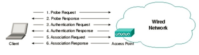
Below figure shows the 802.11 exchange protocol for a client device in an infrastructure network.
Authentication and association frame types are unidirectional. For example, the client device will be the one transmitting the association request frame and likewise the AP/router will be the one to respond back with the association response frame.
Use the Wireshark display filter to filter down to the traces of interest. Refer to Wireshark website for more information on display filter settings.
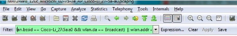
As an example, enter into the display filter
(wlan.bssid == Cisco-Li_27:5a:a0 && wlan.da == Broadcast) || wlan.addr == Microchi_02:75:7e
In our example, Cisco-Li_27:5a:a0 represents the AP/router and Microchi_02:75:7e represents the wireless client.
• More examples of display filter
Wlan.fc.type == 0 Management frames
Wlan.fc.type == 1 Control frames
Wlan.fc.type == 2 Data frames
Wlan.fc.type_subtype == 0 Association request
Wlan.fc.type_subtype == 1 Association response
Wlan.fc.type_subtype == 2 Reassociation request
Wlan.fc.type_subtype == 3 Reassociation response
Wlan.fc.type_subtype == 4 Probe request
Wlan.fc.type_subtype == 5 Probe response
Wlan.fc.type_subtype == 8 Beacon
Wlan.fc.type_subtype == 10 Disassociation
Wlan.fc.type_subtype == 11 Authentication
Wlan.fc.type_subtype == 12 Deauthentication
Information you are likely to need for the display filter
• BSSID of AP/router
BSSID is unique and identifies a specific AP/router eg Cisco-Li_27:5a:a0
If you can unable to determine the BSSID, an alternative is to review the list of beacons in the wireless packets capture and use this list to narrow down the BSSID.
This will translate to “wlan.bssid == Cisco-Li_27:5a:a0” in the display filter.
• MAC Address of client device eg MRF24W
This will identify the client device’s hardware address.
As an example, the console terminal when using the MRF24W will display a MAC address field.
See below figure where the MAC address is 00:1e:c0:02:75:7e.
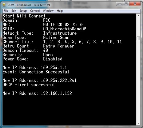
“00:1e:c0:02:75:7e” is translated to “Microchi_02:75:7e”.
Enter “wlan.addr == Microchi_02:75:7e” in the display filter.
• Source Address or Destination address
This could be the following; BSSID field, address field or “Broadcast” or “Multicast”.
Beacons are broadcast frames and the destination address is set as “Broadcast”.
As an example, to display beacons transmitted by a particular AP/router, this will translate to “(wlan.bssid == Cisco-Li_27:5a:a0 && wlan.da == Broadcast) “ in the display filter.
Step 1 : Open the wireless packets capture traces / file.
Step 2: Use the display filter to filter down to the traces of interest.
Step 3 : Active or Passive Scanning
Before wireless connection is established, a client device needs to locate the specific AP/router that it wishes to join by either passive or active scanning.
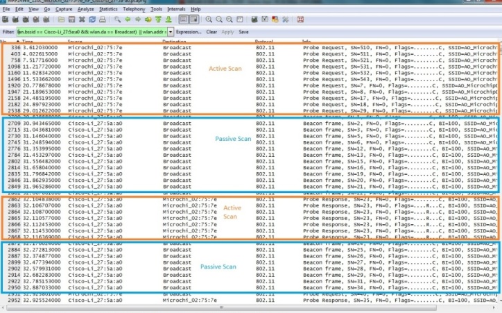
Passive Scanning
Every “unhidden” AP/router will be transmitting beacons almost every beacon interval (BI). The client device is likely to receive multiple beacons from different AP/routers. A scan list result will be generated showing wireless devices or AP/routers that is present in the wireless network.
Each beacon frame will contain information about the infrastructure network such as
o Transmission rate of beacon (Based on 802.11-2007 specifications, transmitted at 1-2Mbps)
o BSSID, source address, destination address
Destination address is often of Broadcast type.
o SSID of infrastructure network
o AP/Router supported rates
![]()
Active Scanning
This involves transmission of broadcast probe request frames by the wireless client device and the AP/routers responding back with a directed (unicast) probe response frames (destination is the same client device that transmits the probe request frames). Likewise, a scan list result will be generated from the probe response frames received.
“Hidden” AP/router
In the case of a “hidden” AP/router, only active scan is used and the wireless client knows the SSID of the wireless network it desires to connect to. The wireless client will transmit a directed probe request frame to this “hidden” AP/router and the “hidden” AP/router will respond back with the corresponding probe response frames.
Refer to the figure below.
Once the wireless client knows the particular infrastructure network it wishes to join, the authentication and association process will be initiated.
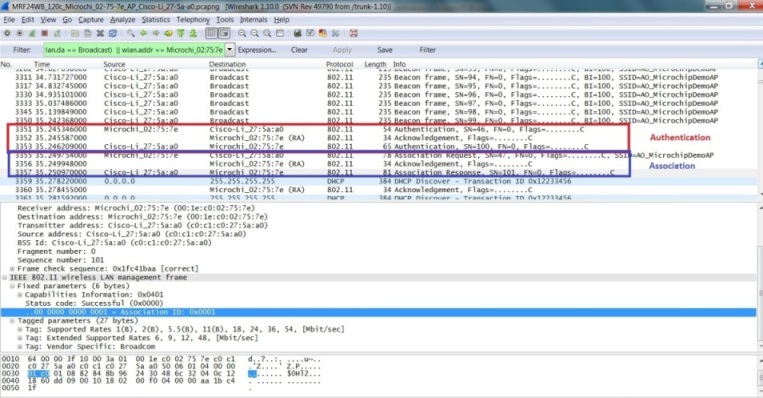
Step 4 : Authentication
To initiate wirelss connection to the AP/router, authentication process will have to first take place.
The wireless client device will transmit a directed authentication frame to the desired AP/router. The AP/Router will respond by transmitting a directed authentication to the same wireless client device to indicate the authentication status.
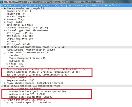
Within the authentication frame from the AP/router, it will contain
o BSSID, source address, destination address
Destination address will be the wireless device which has transmitted the authentication (directed).
o Authentication Algorithm
This contained the authentication algorithm used, such as Open System.
o Status Code
Status Code will indicate whether authentication is a success or failure.
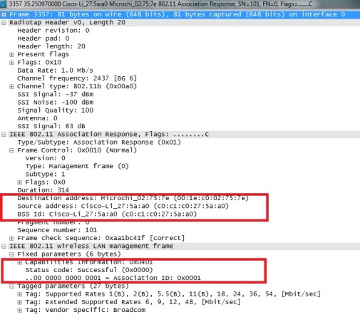
Step 5 : Association
When the authentication process is completed, this will be followed by the association process.
The wireless client device will transmit a directed association request frame to the desired AP/router. The AP/Router will respond by transmitting a directed association response frame to the same wireless device to indicate the association status.
Within the association response frame from the AP/router, it will contain
o BSSID, source address, destination address
Destination address will be the wireless device which has transmitted the association request (directed).
o Status Code and Association ID (AID)
Status Code will indicate whether association is a success or failure. If association is successful, an unique AID will be assigned.
Integration of WPS into 802.11 joining operation
Below lists the overall sequences
• Scanning, Authentication, Association
• WPS Frame Exchanges (EAP protocol)
• Deauthentication or Disassociation
o Some APs are found to transmit disassociation instead of deauthentication frame.
Provision needs to be made to handle receipt of disassociation frame.
• Authentication, Association
• EAPOL 4-way handshake or 802.1X-authentication
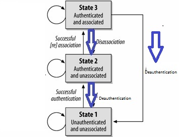
Disconnection from a wireless network
If the device is disconnected according to the 802.11 specifications, either of the following procedures will take place.
• Disassociation
• Deauthentication
Or
• Deauthentication
When an AP sends a deauthentication notice to an associated STA, the association shall also be terminated