Visit the Microchip web site to view the PIC18 Explorer  Product Page.
The PIC18 Explorer is for evaluation of high pin-count PIC18 microcontrollers. By connecting a TCP/IP daughter board to it, you can test and debug Ethernet functionality with a variety of PIC18s. The PIC18F97J60 family includes a built-in Ethernet peripheral, making it the default low-cost, PIC18 Ethernet development platform; the PICDEM.net 2 is the recommended development board for this part.
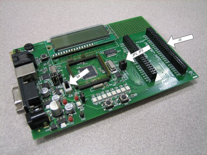
When using the PIC18 Explorer, ensure that jumpers JP2 and JP3 are shorted to enable the LCD and EEPROM, and switch S4 is configured to properly select the on-board PIC or the ICE setting, as your application requires.
Using the Ethernet PICtail
Unlike the PICDEM.net 2, the PIC18 Explorer does not include an ENC28J60 on the board. To enable testing and debugging using the ENC28J60, you must connect an Ethernet PICtail, as shown in the picture (insert header J2 into connector J3 on the demo board).
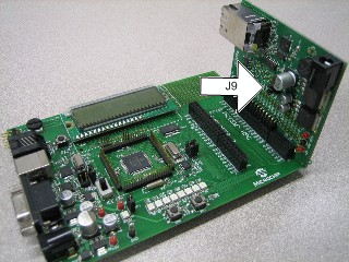
When using this configuration, short pins 2 and 3 on jumper J9, to indicate that the PIC18 Explorer is providing a 5V power supply. The pre-compiled and pre-configured versions of the demo that correspond to this setup are already written to enable ENC28J60 functionality; for manual configuration information, see the ENC28J60 configuration page.
Using the Fast Ethernet PICtail
By connecting the Fast Ethernet PICtail to the PICtail connector on the board, you can use it to test the ENC624J600. To use the Fast Ethernet PICtail, insert it as shown in the picture, with header J4 on the PICtail inserted into connector J3 on the demo board.
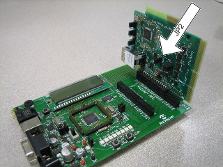
The Fast Ethernet PICtail is designed to use the SPI communication bus when connected through a PICtail header, so the jumper settings are unused in this configuration, with one exception: the JP2 jumper on the PICtail, labeled ISENSE, should be shorted. The pre-compiled and pre-configured versions of the demo that correspond to this setup are already written to enable ENC624J600 functionality; for manual configuration information, see the ENCX24J600 configuration page.
Using the Microchip MRF24WB0MA / MRF24WG0MA 802.11b/g WiFi PICtail
The PIC18 Explorer can be used to debug wireless functionality by connecting the PICtail as show in the picture, with header J1 on the PICtail inserted into connector J3 on the demo board.
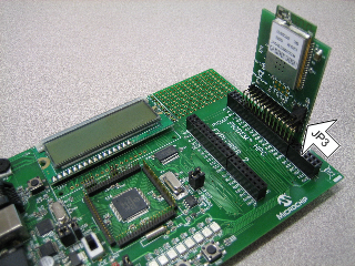
Note if jumper JP3 exists, it must be shorted between pins 2 and 3 when used on this development platform.
Once your hardware is configured, you can program your board with your preferred demo project. The next few topics in the Getting Started section of this help file provide a tutorial for setting up the generic TCPIP demo application.