Bootloader Design
The bootloader is a TFTP server which starts automatically on Power-on Reset (POR). It can be located anywhere within program memory. To cause the automatic startup, the bootloader transparently performs a replacement of the instruction(s) at program memory locations 000000h-000003h. The .hex file to be programmed to the chip by the bootloader will normally contain a GOTO instruction at address 000000h which branches to the main application. Instead of writing the original instruction at address zero, the bootloader creates a new GOTO instruction which always branches to the start address of the bootloader code. The original application instruction at address zero is moved to a jump table, which is later called to exit the bootloader. The jump table also contains a GOTO 000004h instruction to ensure normal application operation if the first instruction was not a GOTO.
If the device is programmed with only the bootloader (no application), address 000000h through the start address of the bootloader code will be in an unprogrammed state (FFFFh). These are NOP instructions which will quickly execute until the program counter reaches the start of the bootloader. This ensures entry into the bootloader for both programmed and unprogrammed parts.
If the running application wants to reenter the bootloader, it should clear the RCON<NOT_POR> bit and then execute a RESET instruction. When the bootloader returns control to the main application, the NOT_POR bit will be in the set state. If an application needs to reset quickly without waiting for the bootloader timeout, it should leave this bit in the set state. This will cause the bootloader to skip its normal operation and return immediately to the application.
Prior to executing the RESET instruction to reenter the bootloader, the main application can specify the MAC and IP address for the bootloader to use. To do this:
- Select a random memory location where 12 bytes can be written
- Copy the MAC address to the chosen memory location at offset 0
- Copy the IP address to the chosen memory location at offset 6
- Compute an IP checksum of the MAC and IP address stored at the memory locations 0 through 9
- Write the IP checksum at the chosen memory location at offset 10
- Store the address of the chosen memory location into the PRODH:PRODL registers
- Clear the RCON<NOT_POR> bit and execute a RESET instruction to enter the bootloader
Upon entry, the bootloader will detect that the RCON<NOT_RI> bit is clear, indicating the bootloader was entered from the main application instead of a genuine POR event. In this case, the bootloader will dereference the PRODH:PRODL pointer, validate the checksum, and if valid, use the MAC and IP address specified. If the checksum is invalid, the bootloader will use it's default compiled MAC and IP address.
The Microchip TCP/IP Stack library provides a Reboot module which can perform the above procedure upon detection of a TFTP packet. When the Reboot module is used, the application IP address (possibly obtained automatically via DHCP) can be used as the TFTP bootloader target. If the IP address used by the main application is Internet routable, then the bootloader itself will be accessible via the Internet.
The entire program memory map when using the bootloader is shown below.
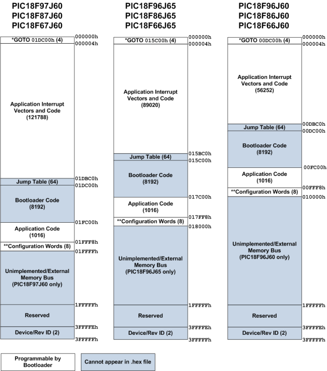
*: GOTO instruction is automatically generated by bootloader when writing. Application instruction at address 000000h is moved to Bootloader Jump Table.
**: Some configuration options are not supported and will automatically be changed by the bootloader before flashing. The bootloader requires HS or HS+PLL oscillator mode and does not support 1:1 and 1:2 Watchdog Timer Postscale modes. Switching between Extended and non-Extended mode is not supported either. (The bootloader must be recompiled to change modes.)
The bootloader uses a block of 8256 bytes of program memory. To prevent the application from inadvertently using this block, you should modify the linker script in your application prior to compiling. For example, for the MPLAB® C18 C compiler, the linker script will contain a CODEPAGE line describing the available Flash memory in the device. For the PIC18F97J60 product with 128kB of program memory, the linker script (18f97j60i.lkr) will contain a line such as:
CODEPAGE NAME=page START=0x2A END=0x1FFF7
This line indicates that the linker can place application constants and code anywhere between 00002Ah and 01FFF7h. This line must be split into two CODEPAGE lines to describe the gap in available program memory occupied by the bootloader. Ex:
CODEPAGE NAME=page START=0x2A END=0x1DBBF
CODEPAGE NAME=page2 START=0x1FC00 END=0x1FFF7
The above example removes the Jump Table and Bootloader Code blocks for the PIC18F97J60 with 128kB of Flash memory. Other devices with less Flash memory will need to use different start and end values according to the Jump Table start address and Bootloader Code end address described in the memory map figure above.
The TFTP server performs a "bulk erase" before starting any TFTP put (write) operation. The erase is not a true bulk erase because the bootloader and configuration words remain intact. However, all other locations are reverted to their unprogrammed state. The erase procedure starts with the Flash page containing the Jump Table and continues backwards in memory towards address 000000h. After address 000000h is erased, the last program memory page containing the device configuration words is erased. For example, assuming a PIC18F97J60 with 128kB of Flash, the erase procedure will follow these steps:
- Erase 01D800h-01DBFFh
- Erase 01D400h-01D7FFh
- Erase 01D000h-01D3FFh
- ...
- Erase 000400h-0007FFh
- Erase 000000h-0003FFh
- Erase 01FC00h-01FFFFh
After the last page containing the configuration words are erased, the configuration words are immediately reprogrammed to their previous value. This algorithm provides very robust operation with an extremely low likelihood of destroying access to the bootloader due to an unexpected event (ex: power or network connectivity is lost while bootloading). Unexpected events will leave the first GOTO instruction at address 000000h intact, ensuring that the bootloader will start up again. Because the configuration words are erased last, there will not be any means of circumventing the internal code protect feature while application code still remains in the device.
Program operations are performed sequentially starting at address 000000h and growing upwards, as presented in the .hex file to be programmed. The device configuration words are typically the last values encountered in the .hex file. Because the erase procedure involves clearing the configuration words and then immediately reprogramming them, the configuration words will already be programmed by the time the configuration words are encountered in the .hex file. Therefore, if the .hex file contains different configuration words from what are already stored in the Flash memory, the bootloader will have to perform a new erase operation on the last page prior to programming the new configuration words. This extra erase/write cycle will reduce overall Flash endurance on the last page as compared to the rest of the device. However, the bootloader will not perform this erase/write if the configuration words have not changed. This feature preserves endurance for most application firmware upgrades, which typically do not require different configuration options to be programmed.
To save code space, the bootloader currently only supports reading through the TFTP server as binary data. Instead of getting a .hex file from a TFTP get operation, the bootloader will send back a binary file sized to the amount of internal Flash memory available (128kB for PIC18F97J60, 64kB for PIC18F66J60, etc.). The bootloader verifies code immediately after programming devices, so the read feature is primarily for debugging only.
Read operations are disabled if the currently programmed application has the PIC® microcontroller Code Protect feature turned on.