Visit the Microchip web site to view the Explorer 16  Product Page and the PIC32 Starter Kit Product Page.
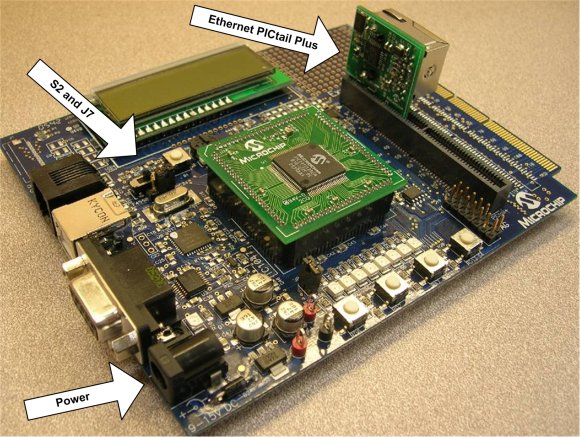
The Explorer 16 board is an all-purpose demonstration and development board for 16-bit and 32-bit parts. It can be expanded for TCP/IP support using the Ethernet PICtail Plus, Fast 100Mbps Ethernet PICtail Plus, or 802.11b WiFi PICtail Plus daughter board.
Before using the Explorer 16, check that:
- Switch S2 selects PIM
- Jumper J7 selects PIC24 (even though the label reads PIC24, this jumper setting selects the programming signals to any PIC on the Explorer 16).
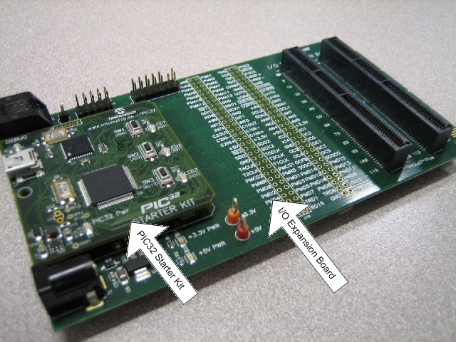
The PIC32 Starter Kit performs a similar function for 32-bit PIC32 parts. By using the PIC32 I/O Expansion Board you can connect the same PICtail Plus board that connect to the Explorer 16.
Using the Ethernet PICtail Plus
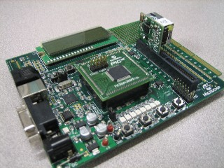
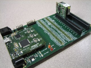
To enable testing and debugging of the ENC28J60 on these boards, you must connect an Ethernet PICtail Plus, as shown in the picture (insert header J2 into the upper card-edge connector J5 (Explorer 16) or J4 (I/O Expansion Board)). Note that for some demos, the Ethernet PICtail Plus will need to be inserted into the center card-edge connector of the PICtail Plus connector to use the SPI2 module. See the Demo Compatibility Table for more information.
The pre-compiled and pre-configured versions of the demo that correspond to this setup are already written to enable ENC28J60 functionality; for manual configuration information, see the ENC28J60 configuration page.
Using the Fast Ethernet PICtail Plus
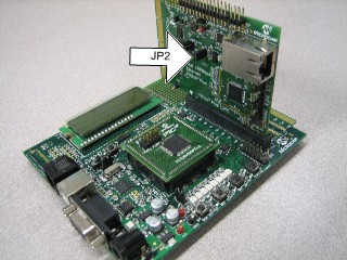
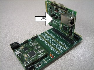
By connecting the Fast 10/100 Ethernet PICtail Plus to the PICtail Plus connector on your board, you can use it to test the ENC624J600. The Fast Ethernet PICtail Plus can be used with these boards in either serial (SPI) or parallel communication mode. For serial mode, connect header J2 of the daughter board to connector J5 (Explorer 16) or J4 (I/O Expansion Board), as seen in the pictures. When operating in serial mode, the jumpers on the Fast Ethernet PICtail are unused, with one exception: the JP2 jumper on the PICtail, labeled ISENSE, should be shorted.
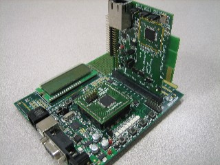
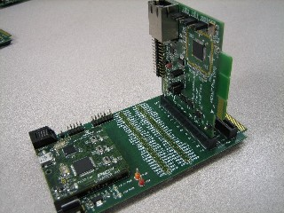
To use the Fast Ethernet PICtail Plus board in parallel mode, insert header J1 into connector J5 of the Explorer 16 or J4 of the I/O Expansion Board, as seen in the pictures. In this configuration, the jumpers must be shorted or opened corresponding to the parallel communication mode being used. A matrix outlining which jumper connections must be made for the jumpers labeled PSPCFG3, PSPCFG2, PSPCFG1&4, PMA to AD, and PMA to A is printed on the back side of the daughter board.
The pre-compiled and pre-configured versions of the demo that correspond to this setup are already written to enable ENC624J600 functionality; for manual configuration information, see the ENCX24J600 configuration page.
Using the Microchip MRF24WB0MA / MRF24WG0MA WiFi PICtail
The Explorer 16 and PIC32 Starter Kit can be used to debug wireless functionality by connecting the PICtail as show in the pictures, with header J2 on the PICtail inserted into the top slot of connector J5 (Explorer 16) or J4 (I/O Expansion Board) on the demo boards.
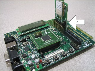
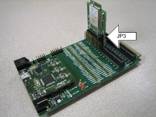
Note if jumper JP3 exists, it must be shorted between pins 1 and 2 when used on this development platform.
Once your hardware is configured, you can program your board with your preferred demo project. The next few topics in the Getting Started section of this help file provide a tutorial for setting up the generic TCP/IP demo application.