|
Audience |
Advanced |
|
Length |
75 minutes |
|
Prerequisites |
Complete Simulating an Orbit, Simple Orbit Transfer, Mars B-Plane Targeting and a basic understanding of B-Planes and their usage in targeting is required. |
|
Script and function Files |
|
Note
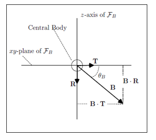
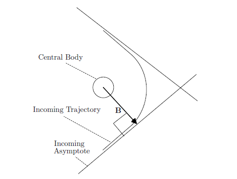
One of the most challenging problems in space mission design is to design an interplanetary transfer trajectory that takes the spacecraft within a very close vicinity of the target planet. One possible approach that puts the spacecraft close to a target planet is by targeting the B-Plane of that planet. The B-Plane is a planar coordinate system that allows targeting during a gravity assist. It can be thought of as a target attached to the assisting body. In addition, it must be perpendicular to the incoming asymptote of the approach hyperbola. Figure 10.1, “Geometry of the B-Plane as seen from a viewpoint perpendicular to the B-Plane” and Figure 10.2, “The B-vector as seen from a viewpoint perpendicular to orbit plane” show the geometry of the B-Plane and B-vector as seen from a viewpoint perpendicular to orbit plane. To read more on B-Planes, please consult the GMATMathSpec document. A good example involving the use of B-Plane targeting is a mission to Mars. Sending a spacecraft to Mars can be achieved by performing a Trajectory Correction Maneuver (TCM) that targets Mars B-Plane. Once the spacecraft gets close to Mars, then an orbit insertion maneuver can be performed to capture into Mars orbit.
In this tutorial, we will use GMAT to model a mission to Mars with the emphasis of how to use GMAT functions. Starting from an out-going hyperbolic trajectory around Earth, we will perform a TCM to target Mars B-Plane. Once we are close to Mars, we will adjust the size of the maneuver to perform a Mars Orbit Insertion (MOI) to achieve a final elliptical orbit with an inclination of 90 degrees. Meeting these mission objectives requires us to create two separate targeting sequences. In order to focus on the configuration of the two targeters, we will make extensive use of the default configurations for spacecraft, propagators, and maneuvers.
The first target sequence employs maneuvers in the Earth-based Velocity (V), Normal (N) and Bi-normal (B) directions and includes four propagation sequences. The purpose of the maneuvers in VNB directions is to target BdotT and BdotR components of the B-vector. BdotT is targeted to 0 km and BdotR is targeted to a non-zero value to generate a polar orbit that has inclination of 90 degrees. BdotR is targeted to -7000 km to avoid having the orbit intersect Mars, which has a radius of approximately 3396 km. The entire first target sequence will be created inside a GMAT function. In the Mission tree, this function will be called through GMAT's CallGmatFunction command. Additionally, we'll go ahead and declare pertinent objects (e.g. spacecraft, force models, subscribers, impulsive burns etc.) as global in both the main script and inside the function through GMAT's Global command.
The second target sequence employs a single, Mars-based anti-velocity direction (-V) maneuver and includes one propagation sequence. This single anti-velocity direction maneuver will occur at periapsis. The purpose of the maneuver is to achieve MOI by targeting position vector magnitude of 12,000 km at apoapsis. Unlike the first target sequence, the second target sequence will not be created inside a function.
The purpose behind this tutorial is to demonstrate how GMAT functions are created, populated, called-upon and used as part of practical mission design. In this tutorial, we'll deliberately put the entire first target sequence inside a GMAT function. Next in the Mission tree, we'll call and execute the function, then continue with the design of the second target sequence outside of the function. Key objects such as the spacecraft, force models, subscribers etc. will be declared global in order to assure continuous flow of data is plotted and reported to all the subscribers. The basic steps of this tutorial are:
-
Modify the
DefaultSCto define spacecraft’s initial state. The initial state is an out-going hyperbolic trajectory that is with respect to Earth. -
Create and configure a
Fuel Tankresource. -
Create two
ImpulsiveBurnresources with default settings. -
Create and configure three
Propagators:NearEarth, DeepSpace and NearMars -
Create and configure
DifferentialCorrectorresource. -
Create and configure three
DefaultOrbitViewresources to visualize Earth, Sun and Mars centered trajectories. -
Create and configure single
ReportFileresource that will be used in reporting data. -
Create and configure three
CoordinateSystems:Earth, Sun and Mars centered. -
Create and configure single
GmatFunctionresource that will be called and executed in the Mission tree. -
Create first
Targetsequence inside the GMAT function. This sequence will be used to target BdotT and BdotR components of the B-vector. -
Create second
Targetsequence to implement MOI by targeting position magnitude at apoapsis. -
Run the mission and analyze the results.
For this tutorial, you’ll need GMAT open, with the default mission
loaded. To load the default mission, click New Mission
( ) or start a new GMAT session.
DefaultSC will be modified to set spacecraft’s
initial state as an out-going hyperbolic trajectory.
) or start a new GMAT session.
DefaultSC will be modified to set spacecraft’s
initial state as an out-going hyperbolic trajectory.
We need to create a fuel tank in order to see how much fuel is expended after each impulsive burn. We will modify DefaultSC resource later and attach the fuel tank to the spacecraft.
-
In the Resources tree, right-click the Hardware folder, point to Add and click ChemicalTank. A new resource called ChemicalTank1 will be created.
-
Right-clickChemicalTank1 and click Rename.
-
In theRename box, type MainTank and click OK.
-
Double click onMainTank to edit its properties.
-
Set the values shown in the table below.
-
Click OK to save these changes.
We need to make minor modifications to DefaultSC in order to define spacecraft’s initial state and attach the fuel tank to the spacecraft.
-
In the Resources tree, under Spacecraft folder, right-click DefaultSC and click Rename.
-
In the Rename box, type MAVEN and click OK.
-
Double-click on MAVEN to edit its properties. Make sure Orbit tab is selected.
-
Set the values shown in the table below.
Table 10.2. MAVEN settings
Field Value Epoch Format UTCGregorian Epoch 18 Nov 2013 20:26:24.315Coordinate System EarthMJ2000Eq State Type Keplerian SMA under Elements -32593.21599272796ECC under Elements 1.202872548116185INC under Elements 28.80241266404142RAAN under Elements 173.9693759331483AOP under Elements 240.9696529532764TA under Elements 359.9465533778069
-
Click on Tanks tab now.
-
Under Available Tanks, you'll see MainTank. This is the fuel tank that we created earlier.
-
We attach MainTank to the spacecraft MAVEN by bringing it under Selected Tanks box. Select MainTank under Available Tanks and bring it over to the right-hand side under the Selected Tanks.
-
Click OK to save these changes.
We’ll need two ImpulsiveBurn resources for this tutorial. Below, we’ll rename the default ImpulsiveBurn and create a new one. We’ll also select the fuel tank that was created earlier in order to access fuel for the burns.
-
In the Resources tree, under the Burns folder, right-click DefaultIB and click Rename.
-
In the Rename box, type TCM, an acronym for Trajectory Correction Maneuver and click OK to edit its properties.
-
Double-Click TCM to edit its properties.
-
Check Decrement Mass under Mass Change.
-
For Tank field under Mass Change, select MainTank from drop down menu.
-
Click OK to save these changes.
-
Right-click theBurns folder, point to Add, and click ImpulsiveBurn. A new resource called ImpulsiveBurn1 will be created.
-
Rename the new ImpulsiveBurn1 resource to MOI, an acronym for Mars Orbit Insertion and click OK.
-
Double-click MOI to edit its properties.
-
For Origin field under Coordinate System, select Mars.
-
Check Decrement Mass under Mass Change.
-
For Tank field under Mass Change, select MainTank from the drop down menu.
-
Click OK to save these changes.
We’ll need to add three propagators for this tutorial. Below, we’ll rename the default DefaultProp and create two more propagators.
-
In the Resources tree, under the Propagators folder, right-click DefaultProp and click Rename.
-
In the Rename box, type NearEarth and click OK.
-
Double-click on NearEarth to edit its properties.
-
Set the values shown in the table below.
Table 10.3. NearEarth settings
Field Value Initial Step Size under Integrator 600Accuracy under Integrator 1e-013Min Step Size under Integrator 0Max Step Size under Integrator 600Model under Gravity JGM-2 Degree under Gravity 8Order under Gravity 8Atmosphere Model under Drag None Point Masses under Force Model Add Luna and Sun Use Solar Radiation Pressure under Force Model Check this field
-
Click on OK to save these changes.
-
Right-click the Propagators folder and click Add Propagator. A new resource called Propagator1 will be created.
-
Rename the new Propagator1 resource to DeepSpace and click OK.
-
Double-click DeepSpace to edit its properties.
-
Set the values shown in the table below.
Table 10.4. DeepSpace settings
Field Value Type under Integrator PrinceDormand78 Initial Step Size under Integrator 600Accuracy under Integrator 1e-012Min Step Size under Integrator 0Max Step Size under Integrator 864000Central Body under Force Model Sun Primary Body under Force Model None Point Masses under Force Model Add Earth, Luna, Sun, Mars, Jupiter, Neptune, Saturn, Uranus, Venus Use Solar Radiation Pressure under Force Model Check this field
-
Click OK to save these changes.
-
Right-click the Propagators folder and click Add Propagator. A new resource called Propagator1 will be created.
-
Rename the new Propagator1 resource to NearMars and click OK.
-
Double-click on NearMars to edit its properties.
-
Set the values shown in the table below.
Table 10.5. NearMars settings
Field Value Type under Integrator PrinceDormand78 Initial Step Size under Integrator 600Accuracy under Integrator 1e-012Min Step Size under Integrator 0Max Step Size under Integrator 86400Central Body under Force Model Mars Primary Body under Force Model Mars Model under Gravity Mars-50C Degree under Gravity 8Order under Gravity 8Atmosphere Model under Drag None Point Masses under Force Model Add Sun Use Solar Radiation Pressure under Force Model Check this field
-
Click OK to save the changes.
Two Target sequences that we will create
later need a DifferentialCorrector resource to
operate, so let’s create one now. We'll leave the settings at their
defaults.
-
In the Resources tree, expand the Solvers folder if it isn’t already.
-
Right-click the Boundary Value Solvers folder, point to Add, and click DifferentialCorrector. A new resource called DC1 will be created.
-
Rename the new DC1 resource to DefaultDC and click OK.
The BdotT and BdotR constraints that we will define later under the first Target sequence require us to create a coordinate system. Orbit View resources that we will create later also need coordinate system resources to operate. We will create Sun and Mars centered coordinate systems. So let’s create them now.
-
In the Resources tree, right-click the Coordinate Systems folder and click Add Coordinate System. A new Dialog box is created with a title New Coordinate System.
-
Type SunEcliptic under Coordinate System Name box.
-
Under Origin field, select Sun.
-
For Type under Axes, select MJ2000Ec.
-
Click OK to save these changes. You’ll see that a new coordinate system SunEcliptic is created under Coordinate Systems folder.
-
Right-click the Coordinate Systems folder and click Add Coordinate System. A new Dialog Box is created with a title New Coordinate System.
-
Type MarsInertial under Coordinate System Name box.
-
Under Origin field, select Mars.
-
For Type under Axes, select BodyInertial.
-
Click OK to save these changes. You’ll see that a new coordinate system MarsInertial is created under Coordinate Systems folder.
We’ll need three DefaultOrbitView resources for this tutorial. Below, we’ll rename the default DefaultOrbitView and create two new ones. We need three graphics windows in order to visualize spacecraft’s trajectory centered around Earth, Sun and then Mars
-
In the Resources tree, under Output folder, right-click DefaultOrbitView and click Rename.
-
In the Rename box, type EarthView and click OK.
-
In the Output folder, delete DefaultGroundTrackPlot.
-
Double-click EarthView to edit its properties.
-
Set the values shown in the table below.
Table 10.6. EarthView settings
Field Value View Scale Factor under View Definition 4View Point Vector boxes, under View Definition 0, 0, 30000
-
Click OK to save these changes.
-
Right-click the Output folder, point to Add, and click OrbitView. A new resource called OrbitView1 will be created.
-
Rename the new OrbitView1 resource to SolarSystemView and click OK.
-
Double-click SolarSystemView to edit its properties.
-
Set the values shown in the table below.
Table 10.7. SolarSystemView settings
Field Value From Celestial Object under View Object, add following objects to Selected Celestial Object box Mars, Sun (Do not remove Earth) Coordinate System under View Definition SunEcliptic View Point Reference under View Definition Sun View Point Vector boxes, under View Definition 0, 0, 5e8View Direction under View Definition Sun Coordinate System under View Up Definition SunEcliptic
-
Click OK to save these changes.
-
Right-click the Output folder, point to Add, and click OrbitView. A new resource called OrbitView1 will be created.
-
Rename the new OrbitView1 resource to MarsView and click OK.
-
Double-click MarsView to edit its properties.
-
Set the values shown in the table below.
Table 10.8. MarsView settings
Field Value From Celestial Object under View Object, add following object to Selected Celestial Object box Mars (You don’t have to remove Earth) Coordinate System under View Definition MarsInertial View Point Reference under View Definition Mars View Point Vector boxes, under View Definition 22000, 22000, 0View Direction under View Definition MarsCoordinate System under View Up Definition MarsInertial
-
Click OK to save the changes.
We’ll need a single ReportFile resource for this tutorial that we'll use to report data to.
-
Right-click the Output folder, point to Add, and click ReportFile. A new resource called ReportFile1 will be created.
-
Rename the new ReportFile1 resource to rf and click OK.
-
Double-Click rf to edit its properties.
-
Empty the Parameter List by clicking on the Edit button.
-
Click OK to save these changes.
We’ll need a single GMATFunction resource for this tutorial. The first target sequence will be implemented inside this function.
-
Right-click the Functions folder, point to Add, point to GMAT Function and click New.
-
A new GMAT function panel will open. Type the following name for the function TargeterInsideFunction and click OK to save these changes.
-
Now open TargeterInsideFunction resource and paste the below shown first targeter sequence snippet into this function.
-
After pasting of the below snippet is done, click on Save As button and save your function. After saving your function, close TargeterInsideFunction resource by clicking on the Close button.
          % Target Desired B-Plane Coordinates in this function:

function TargeterInsideFunction()

BeginMissionSequence

Global 'Make Objects Global' MAVEN DeepSpace_ForceModel DefaultDC ...
EarthView MainTank MarsView MOI NearEarth_ForceModel ...
NearMars_ForceModel rf SolarSystemView TCM


Target 'Target B-plane coordinates' DefaultDC {SolveMode = Solve, ...
	ExitMode = SaveAndContinue}
   Propagate 'Prop 3 days' NearEarth(MAVEN) {MAVEN.ElapsedDays = 3}
   Propagate 'Prop 12 Days to TCM' DeepSpace(MAVEN) {MAVEN.ElapsedDays = 12}
   Vary 'Vary TCM.V' DefaultDC(TCM.Element1 = 0.001, ...
	{Perturbation = 0.00001, MaxStep = 0.002})
   Vary 'Vary TCM.N' DefaultDC(TCM.Element2 = 0.001, ...
	{Perturbation = 0.00001, MaxStep = 0.002})
   Vary 'Vary TCM.B' DefaultDC(TCM.Element3 = 0.001, ...
	{Perturbation = 0.00001, MaxStep = 0.002})
   Maneuver 'Apply TCM' TCM(MAVEN)
   Propagate 'Prop 280 Days' DeepSpace(MAVEN) {MAVEN.ElapsedDays = 280}
   Propagate 'Prop to Mars Periapsis' NearMars(MAVEN) {MAVEN.Mars.Periapsis}
   Achieve 'Achieve BdotT' DefaultDC(MAVEN.MarsInertial.BdotT = 0, ...
	{Tolerance = 0.00001})
   Achieve 'Achieve BdotR' DefaultDC(MAVEN.MarsInertial.BdotR = -7000, ...
	{Tolerance = 0.00001})
EndTarget;

% Report MAVEN parameters to global 'rf' :
Report 'Report Parameters' rf MAVEN.UTCGregorian TCM.Element1 ...
TCM.Element2 TCM.Element3 MAVEN.MarsInertial.BdotT ...
MAVEN.MarsInertial.BdotR MAVEN.MarsInertial.INC
Reminder that the first target sequence will target desired B-Plane coordinates which will get the spacecraft MAVEN close to Mars. Note that we have declared all the pertinent objects as global at the beginning of the function. These same objects will also be declared global in the Mission Sequence as well. Notice that in this first target sequence, spacecraft MAVEN props for 3 days using NearEarth propagator. Next using the DeepSpace propagator, we propagate for 12 days and execute TCM impulsive maneuver. Again using the DeepSpace propagator, we propagate for another 280 days and finally propagate to Mars Periapsis. The desired constraints of the B-Plane coordinates are to be met at the Mars periapsis. The three components of the TCM impulsive burn are the controls that will help us achieve these two constraints. Note that the tolerances on the two B-Plane constraints are relatively tight.
Now we are ready to configure the Mission Sequence. We will first insert a Global command and declare the same objects as global that were declared global inside the TargeterInsideFunction function. Next we'll insert CallGmatFunction command which will call and initiate our TargeterInsideFunction function that contains our first target sequence. The first target sequence will solve for the TCM maneuver values required to achieve BdotT and BdotR components of the B-vector. BdotT will be targeted to 0 km and BdotR is targeted to a non-zero value in order to generate a polar orbit that will have an inclination of 90 degrees.
The second target sequence employs a single, Mars-based anti-velocity direction (-V) maneuver and includes one propagation sequence. This single anti-velocity direction maneuver will occur at periapsis. The purpose of the maneuver is to achieve MOI by targeting position vector magnitude of 12,000 km at apoapsis. The basic steps of this tutorial are:
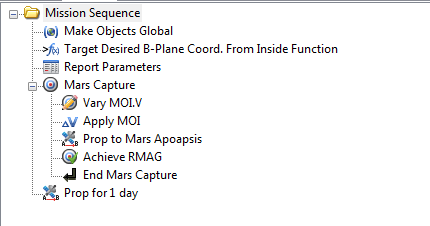
Now create the commands necessary to perform the first Target sequence. Figure 10.3, “Mission Sequence for the First Target sequence” illustrates the configuration of the Mission tree after you have completed the steps in this section.
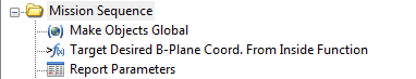
Do following steps to set-up for the first Target sequence:
-
Click on the Mission tab to show the Mission tree.
-
You’ll see that there already exists a Propagate1 command. We need to delete this command
-
Right-click on Propagate1 command and click Delete.
-
Right-click on Mission Sequence folder, point to Append, and click Global. A new command called Global1 will be created.
-
Right-click Global1 and click Rename. In the Rename box, type Make Objects Global and click OK.
-
Right-click on Mission Sequence folder, point to Append, and click CallGmatFunction. A new command called CallGmatFunction1 will be created.
-
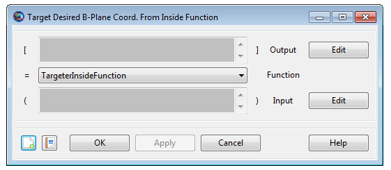
Right-click CallGmatFunction1 and click Rename. In the Rename box, type Target Desired B-Plane Coord. From Inside Function and click OK.
-
Right-click on Mission Sequence folder, point to Append, and click Report. A new command called Report1 will be created.
-
Right-click Report1 and click Rename. In the Rename box, type Report Parameters and click OK.
Now that the structure is created, we need to configure various parts of the first Target sequence to do what we want.
-
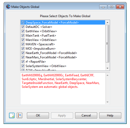
Double-click Make Objects Global to edit its properties.
-
Under Please Select Objects to Make Global check all the available object and make all available objects as global. Recall that same objects were declared as global inside TargeterInsideFunction function as well.
-
Click OK to save these changes.
-
Double-click Target Desired B-Plane Coord. From Inside Function to edit its properties.
-
Under Function, select TargeterInsideFunction from drop down menu. In this particular example, since we're not passing any input(s) or receiving any output(s) to and from the function, hence we won't be editing Input/Output menu.
-
Click OK to save these changes.
-
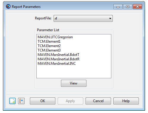
Double-click Report Parameters to edit its properties.
-
Under ReportFile, make sure rf is selected from the from drop down menu.
-
Under Parameter List click on View. This opens up a new ParameterSelectDialog panel. Make sure to select the parameters that are shown in the below Report Parameters screenshot image.
-
Click OK to save these changes.
Before running the mission, click Save
( ) and save the mission to a file of your choice. Now
click Run (
) and save the mission to a file of your choice. Now
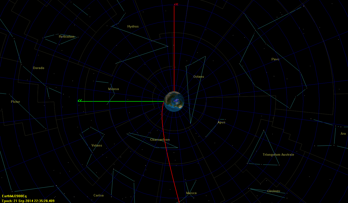
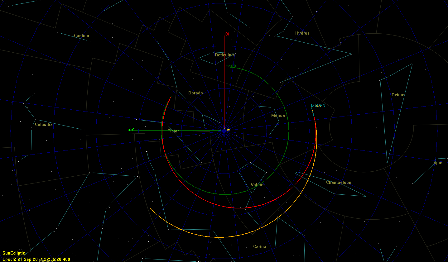
click Run ( ). As the mission runs, you will see GMAT solve the
targeting problem. Each iteration and perturbation is shown in
EarthView, SolarSystemView and
MarsView windows in light blue, and the final
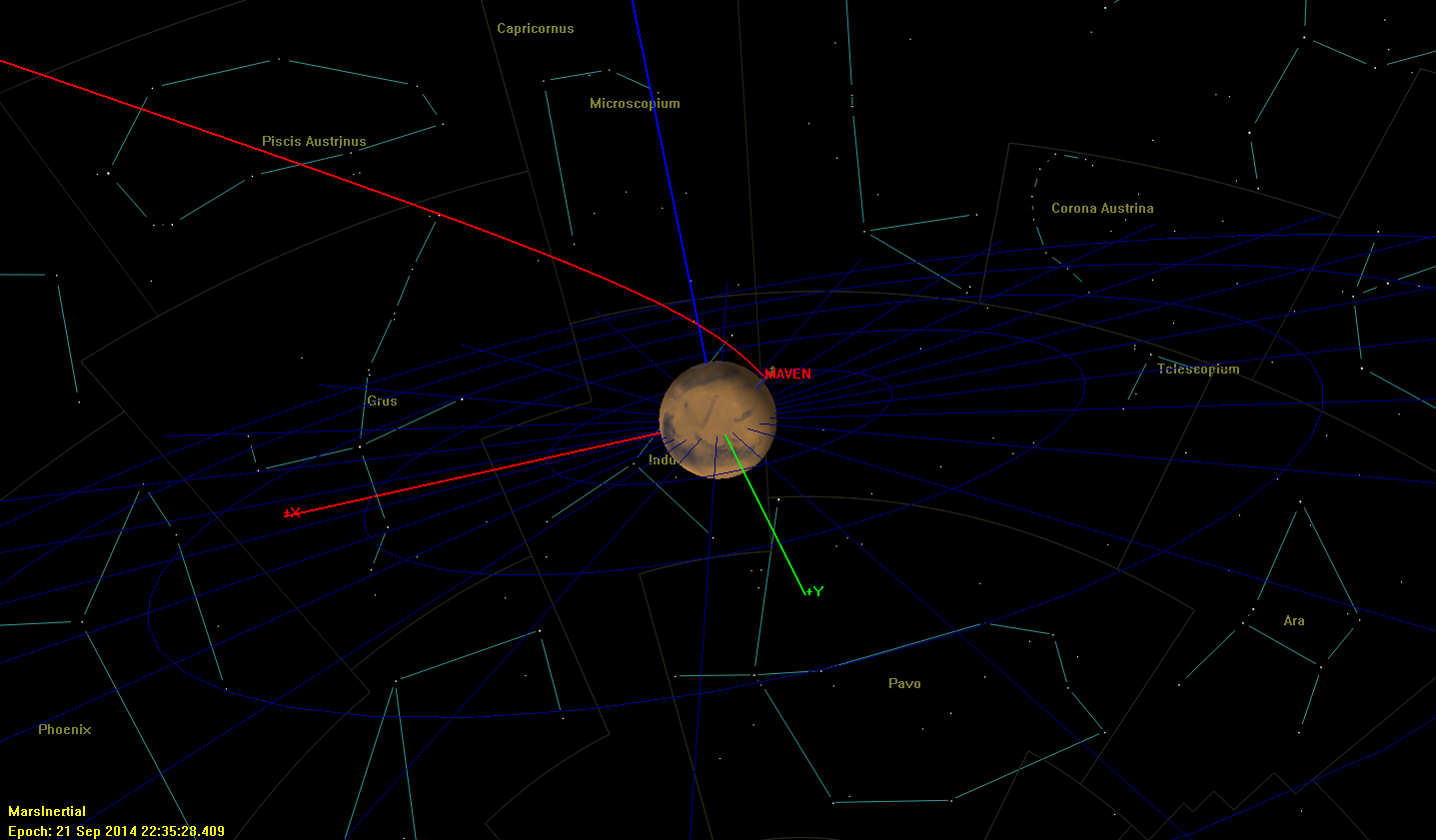
solution is shown in red. After the mission completes, the 3D views should
appear as in the images shown below. You may want to run the mission
several times to see the targeting in progress.
). As the mission runs, you will see GMAT solve the
targeting problem. Each iteration and perturbation is shown in
EarthView, SolarSystemView and
MarsView windows in light blue, and the final
solution is shown in red. After the mission completes, the 3D views should
appear as in the images shown below. You may want to run the mission
several times to see the targeting in progress.
Now go to the Output tree and open rf. Recall that rf was declared as a global object both inside the function and in the main script. Notice that both the controls (i.e. TCM burn elements) and constraints (i.e. BdotT, BdotR) are reported as well as MAVEN inclination relative to MarsInertial coordinate system. The desired constraints that were set in the first targeter sequence have been successfully achieved.
Now go back to Mission tree and right click on Target Desired B-Plane Coord. From Inside Function command and click on Command Summary option. Under Coordinate System drop down menu, select MarsIntertial and study the command summary. This command summary corresponds to the very last Propagate command (i.e. 'Prop to Mars Periapsis') from inside the GMAT function. Under Hyperbolic Parameters, notice the values of BdotT and BdotR. These are the constraints that have been achieved on the very last 'Prop to Mars Periapsis' Propagate command from the first targeter which was set up inside the GMAT function.
Recall that we still need to create second Target sequence in order to perform Mars Orbit Insertion maneuver to achieve the desired capture orbit. In the Mission tree, we will create the second Target sequence right after the first Target sequence which was defined inside the GMAT function TargeterInsideFunction.
Now let’s create the commands necessary to perform the second Target sequence. Figure 10.10, “Mission Sequence showing first and second Target sequences” illustrates the configuration of the Mission tree after you have completed the steps in this section. Notice that in Figure 10.10, “Mission Sequence showing first and second Target sequences”, the second Target sequence is created after the first Target sequence which was called via the CallGmatFunction command. We’ll discuss the second Target sequence after it has been created.
To create the second Target sequence:
-
Click on the Mission tab to show the Mission tree.
-
In the Mission tree, right-click on Mission Sequence folder, point to Append, and click Target. This will insert two separate commands: Target1 and EndTarget1.
-
Right-click Target1 and click Rename.
-
Type Mars Capture and click OK.
-
Right-click Mars Capture, point to Append, and click Vary. A new command called Vary4 will be created.
-
Right-click Vary4 and click Rename.
-
In the Rename box, type Vary MOI.V and click OK.
-
Complete the Target sequence by appending the commands in Table 10.9, “Additional Second Target Sequence Commands”.
Table 10.9. Additional Second Target Sequence Commands
Command Name Maneuver Apply MOIPropagate Prop to Mars ApoapsisAchieve Achieve RMAG
Note
Let’s discuss what the second Target sequence does. We know that a maneuver is required for the Mars capture orbit. We also know that the desired radius of capture orbit at apoapsis must be 12,000 km. However, we don’t know the size (or ΔV magnitude) of the MOI maneuver that will precisely achieve the desired orbital conditions. You use the second Target sequence to solve for that precise maneuver value. You must tell GMAT what controls are available (in this case, a single maneuver) and what conditions must be satisfied (in this case, radius magnitude value). Once again, just like in the first Target sequence, here we accomplish this by using the Vary and Achieve commands. Using the Vary command, you tell GMAT what to solve for—in this case, the ΔV value for MOI. You use the Achieve command to tell GMAT what conditions the solution must satisfy—in this case, RMAG value of 12,000 km.
We need a Propagate command after the second Target sequence so that we can see our final orbit.
-
In the Mission tree, right-click End Mars Capture, point to Insert After, and click Propagate. A new Propagate3 command will appear.
-
Right-click Propagate6 and click Rename.
-
Type Prop for 1 day and click OK.
-
Double-click Prop for 1 day to edit its properties.
-
Under Propagator, replace NearEarth with NearMars.
-
Under Parameter, replace MAVEN.ElapsedSeconds with MAVEN.ElapsedDays.
-
Under Condition, replace the value 0.0 with 1.
-
Click OK to save these changes

Now that the structure is created, we need to configure various parts of the second Target sequence to do what we want.
-
Double-click Mars Capture to edit its properties.
-
In the ExitMode list, click SaveAndContinue. This instructs GMAT to save the final solution of the targeting problem after you run it.
-
Click OK to save these changes

-
Double-click Vary MOI.V to edit its properties. Notice that the variable in the Variable box is TCM.Element1. We want MOI.Element1 which is the velocity component of MOI in the local VNB coordinate system. So let’s change that.
-
Next to Variable, click the Edit button.
-
Under Object List, click MOI.
-
In the Object Properties list, double-click Element1 to move it to the Selected Value(s) list. See the image below for results.
-
Click OK to close the ParameterSelectDialog window.
-
In the Initial Value box, type -1.0.
-
In the Perturbation box, type 0.00001.
-
In the Lower box, type -10e300.
-
In the Upper box, type 10e300.
-
In the Max Step box, type 0.1.
-
Click OK to save these changes.


-
Double-click Apply MOI to edit its properties.
-
In the Burn list, click MOI.
-
Click OK to save these changes.

-
Double-click Prop to Mars Apoapsis to edit its properties.
-
Under Propagator, replace NearEarth with NearMars.
-
Under Parameter, replace MAVEN.ElapsedSeconds with MAVEN.Mars.Apoapsis.
-
Click OK to save these changes.

-
Double-click Achieve RMAG to edit its properties.
-
Next to Goal, click the Edit button.
-
In the Object Properties list, click RMAG.
-
Under Central Body, select Mars and double-click on RMAG.
-
Click OK to close the ParameterSelectDialog window.
-
In the Value box, type 12000.
-
Click OK to save these changes.

Before running the mission, click Save
(). This will save the additional changes that we
implemented in the Mission tree. Now click
Run (). The first Target sequence
will converge first after a few iterations.
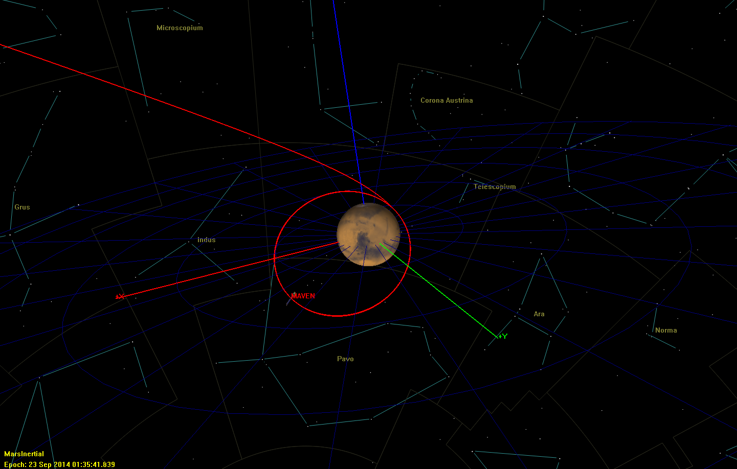
As the mission runs, you will see GMAT solve the second Target sequence’s targeting problem. Each iteration and perturbation is shown in MarsView windows in light blue, and the final solution is shown in red. After the mission completes, the MarsView 3D view should appear as in the image shown below. EarthView and SolarSystemView 3D views are same as before. You may want to run the mission several times to see the targeting in progress.
If you want to know MOI maneuver’s delta-V vector values and how much fuel was expended during the maneuver, do the following steps:
-
In the Mission tree, right-click Apply MOI, and click on Command Summary.
-
Scroll down and under
Maneuver Summaryheading, values for delta-V vector are:Delta V Vector:Element 1: -1.6032580309280 km/sElement 2: 0.0000000000000 km/sElement 3: 0.0000000000000 km/s -
Scroll down and under
Mass depletion from MainTankheading,Delta VandMass Changetells you MOI maneuver’s magnitude and how much fuel was used for the maneuver:Delta V: 1.6032580309280 km/sMass change: -1075.9520121897 kg
Just to make sure that the goal of second Target sequence was met successfully, let us access command summary for Achieve RMAG command by doing the following steps:
-
In the Mission tree, right-click Achieve RMAG, and click on Command Summary.
-
Under Coordinate System, select MarsInertial.
-
Under
Keplerian Stateandand Spherical Stateheadings, see the values ofTAandRMAG. You can see that the desired radius of the capture orbit at apoapsis was achieved successfully:TA = 180.00000085377 degRMAG = 12000.017390989 km