Chapter�7.燭arget Finite Burn to Raise Apogee
From General Mission Analysis Tool
|
Audience |
Intermediate level |
|
Length |
45 minutes |
|
Prerequisites |
Complete Simulating an Orbit and Simple Orbit Transfer |
|
Script File |
|
Note
One of the most common operational problems in space mission design is the design of a finite burn that achieves a given orbital goal. A finite burn model, as opposed to the idealized impulsive burn model used for preliminary design, is needed to accurately model actual spacecraft maneuvers.
In this tutorial, we will use GMAT to perform a finite burn for a spacecraft in low Earth orbit. The goal of this finite burn is to achieve a certain desired apogee radius. Since the most efficient orbital location to affect apoapsis is at periapsis, the first step in this tutorial is to propagate the spacecraft to perigee.
To calculate the duration of the perigee burn needed to achieve a desired apogee radius of 12000 km, we must create the appropriate targeting sequence. The main portion of the target sequence employs a Begin/End FiniteBurn command pair, for a velocity direction maneuver, followed by a command to propagate the spacecraft to orbit apogee.
The basic steps of this tutorial are:
-
Create and configure the Spacecraft hardware and FiniteBurn resources
-
Create the DifferentialCorrector and Target Control Variable
-
Configure the Mission Sequence. To do this, we will
-
Create Begin/End FiniteBurn commands with default settings.
-
Create a Target sequence to achieve a 12000 km apogee radius.
-
-
Run the mission and analyze the results.
For this tutorial, you’ll need GMAT open with the default mission
loaded. To load the default mission, click New
Mission (![]() ) or start a new GMAT session. We will use the
default configurations for the spacecraft (DefaultSC)
and the propagator (DefaultProp).
DefaultSC is configured by default to a near-circular
orbit, and DefaultProp is configured to use Earth as
the central body with a nonspherical gravity model of degree and order 4.
You may want to open the dialog boxes for these objects and inspect them
more closely as we will leave them at their default settings.
) or start a new GMAT session. We will use the
default configurations for the spacecraft (DefaultSC)
and the propagator (DefaultProp).
DefaultSC is configured by default to a near-circular
orbit, and DefaultProp is configured to use Earth as
the central body with a nonspherical gravity model of degree and order 4.
You may want to open the dialog boxes for these objects and inspect them
more closely as we will leave them at their default settings.
To model thrust and fuel use associated with a finite burn, we must create a ChemicalThruster and a ChemicalTank and then attach the newly created ChemicalTank to the ChemicalThruster.
-
In the Resources tree, right-click on the Hardware folder, point to Add, and click ChemicalThruster. A resource named ChemicalThruster1 will be created.
-
In the Resources tree, right-click on the Hardware folder, point to Add, and click ChemicalTank. A resource named ChemicalTank1 will be created.
-
Double-click ChemicalThruster1 to edit its properties.
-
Select the Decrement Mass box so that GMAT will model fuel use associated with a finite burn.
-
Use the drop down menu to the right of the Tank field to select ChemicalTank1 as the fuel source for ChemicalThruster1. Click OK.
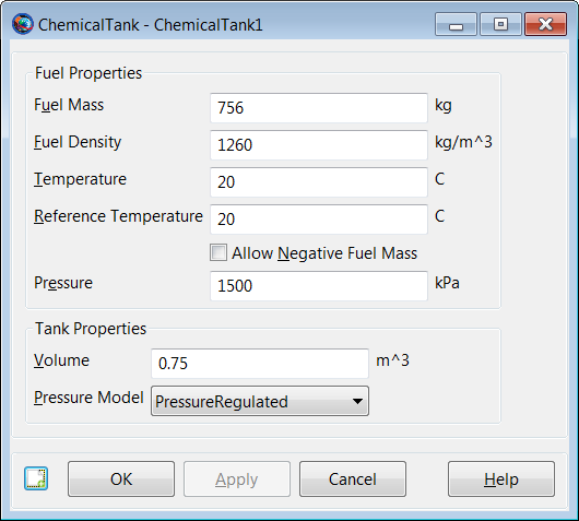
Figure 7.1, “ChemicalTank1 Configuration” below shows the default ChemicalTank1 configuration that we will use and Figure 7.2, “ChemicalThruster1 Configuration” shows the finished ChemicalThruster1 configuration.
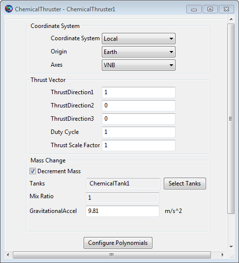
Note that the default Thruster1 Coordinate System, as shown in Figure 7.2, “ChemicalThruster1 Configuration”, is Earth-based Velocity, Normal, Bi-normal (VNB) and that the default Thrust Vector of (1,0,0) represents our desired velocity oriented maneuver direction.
For a general finite burn, if desired, we can specify how both the thrust and the fuel use depend upon fuel tank pressure. The user does this by inputting coefficients of certain pre-defined polynomials. To view the values for the thrust coefficients, click the Edit Thruster Coef. button and to view the ISP coefficients which determine fuel use, click the Edit Impulse Coef. button. For this tutorial, we will use the default ISP polynomial coefficient values but we will change the ChemicalThruster1 polynomial coefficients as follows.
-
In the Resources tree, double-click ChemicalThruster1 to edit its properties
-
Click the Edit Thruster Coef. button to bring up the ThrusterCoefficientDialog box, shown in Figure 7.3, “ChemicalThruster1 Thrust Coefficients”. Replace the default C1 coefficient value of
10with1000. Click OK.
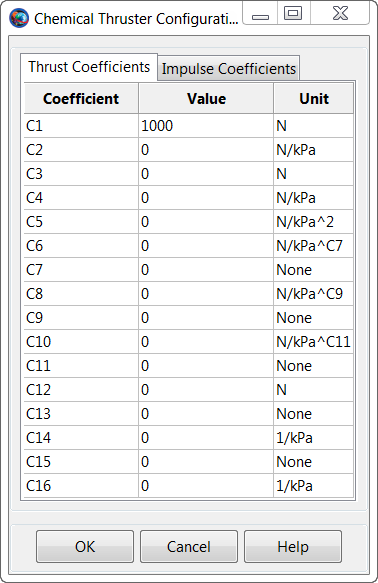
The exact form of the pre-defined Thrust polynomial, associated
with the coefficients above, are given in the
ChemicalThruster help. We note that, by default,
all of the Thrust coefficients associated with terms that involve tank
pressure are zero. We have kept the default zero values for all of these
coefficients. We simply changed the constant term in the Thrust
polynomial from 10 to 1000 which
is much larger than the thrust for a typical chemical thruster. The
Thrust and ISP polynomials used in this tutorial are shown below.
Thrust = 1000 (Newtons)
ISP = 300 (seconds)
-
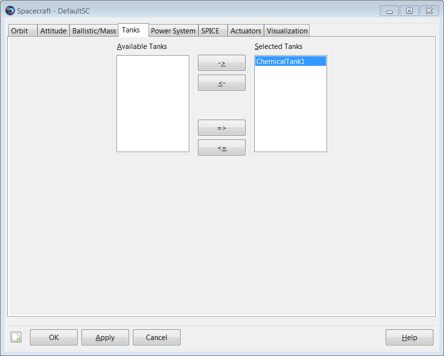
In the Resources tree, double-click DefaultSC to edit its properties.
-
Select the Tanks tab. In the Available Tanks column, select ChemicalTank1. Then click the right arrow button to add ChemicalTank1 to the SelectedTanks list. Click Apply.
-
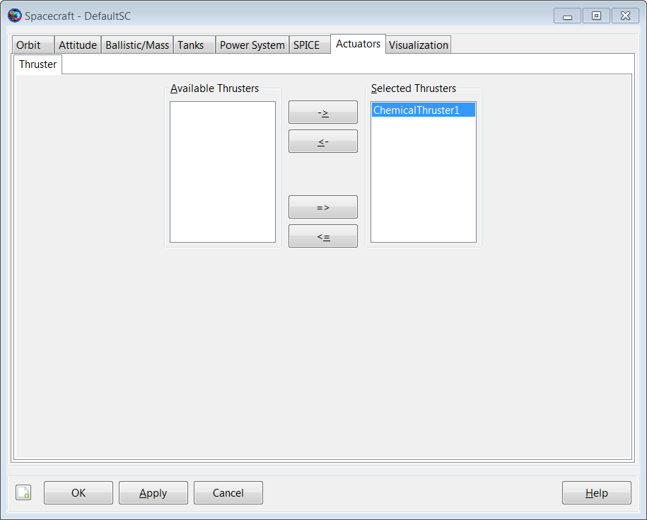
Select the Actuators tab. In the Available Thrusters column, select ChemicalThruster1. Then click the right arrow button to add ChemicalThruster1 to the SelectedThrusters list. Click OK.
We’ll need a single FiniteBurn resource for this tutorial.
-
In the Resources tree, right-click the Burns folder and add a FiniteBurn. A resource named FiniteBurn1 will be created.
-
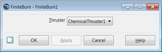
Double-click FiniteBurn1 to edit its properties.
-
Use the menu to the right of the Thruster field to select ChemicalThruster1 as the thruster associated with FiniteBurn1. Click OK.
The Target sequence we will create later needs a DifferentialCorrector resource to operate, so let’s create one now. We'll leave the settings at their defaults.
-
In the Resources tree, expand the Solvers folder if it isn’t already.
-
Right-click the Boundary Value Solvers folder, point to Add, and click DifferentialCorrector. A new resource called DC1 will be created.
The Target sequence we will later create uses
the Vary command to adjust a user defined target
control variable in order to achieve the desired orbital goal of raising
apogee to 12000 km. We must first create this variable
which we will name BurnDuration.
-
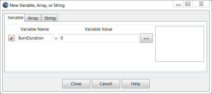
In the Resources tree, right-click the Variables/Arrays/Strings folder, point to Add, and click Variable. A new window will come up with two input fields, Variable Name and Variable Value. For Variable Name, input BurnDuration and for Variable Value, input
0.Click the => button to create the variable, then click Close. -
To verify that we have created this new variable correctly, double-click BurnDuration to view its properties.
Now we will configure a Target sequence to
solve for the finite burn duration required to raise apogee to
12000 km. We’ll begin by creating the initial
Propagate command, then the
Target sequence itself.
-
Click on the Mission tab to show the Mission tree.
-
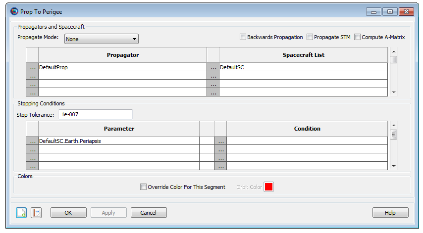
Configure Propagate1 to propagate to DefaultSC.Earth.Periapsis.
-
Rename Propagate1 to Prop To Perigee.
Now create the commands necessary to perform the Target sequence. Figure 7.9, “Final Mission Sequence” illustrates the configuration of the Mission tree after we have completed the steps in this section. We’ll discuss the Target sequence after it has been created.
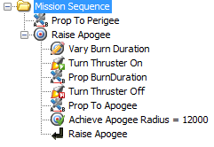
To create the Target sequence:
-
In the Mission tree, right-click Prop To Perigee, point to Insert After, and click Target. This will insert two separate commands: Target1 and EndTarget1.
-
Right-click Target1 and click Rename. Type Raise Apogee and click OK.
-
Right-click Raise Apogee, point to Append, and click Vary. Rename the newly created command as Vary Burn Duration.
-
Right-click Vary Burn Duration, point to Insert After, and click BeginFiniteBurn. Rename the newly created command as Turn Thruster On.
-
Complete the Target sequence by inserting the commands shown in Table 7.1, “Additional Target Sequence Commands”.
Table 7.1. Additional Target Sequence Commands
| Command | Name |
|---|---|
| Propagate |
Prop BurnDuration
|
| EndFiniteBurn |
Turn Thruster Off
|
| Propagate |
Prop To Apogee
|
| Achieve |
Achieve Apogee Radius =
              12000
|
Now that the structure is created, we need to configure the various parts of the Target sequence to do what we want.
-
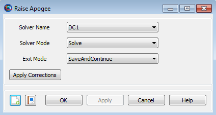
Double-click Raise Apogee to edit its properties.
-
In the ExitMode list, click SaveAndContinue. This instructs GMAT to save the final solution of the targeting problem after you run it.
-
Click OK to save these changes.
-
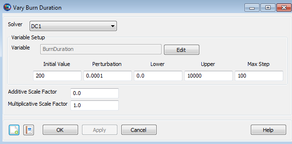
Double-click Vary Burn Duration to edit its properties. We want this command to adjust (or “Vary”) the finite burn duration represented by the previously created control variable, BurnDuration. To accomplish this, click on the Edit button to bring up the ParameterSelectDialog. Use the ObjectType menu to select the Variable object type. The ObjectList menu will then display a list of user defined variables. Double-click on the variable, BurnDuration, so that BurnDuration appears in the SelectedValues(s) menu. Click the OK button to save the changes and return to the Vary Burn Duration command menu.
-
In the Initial Value box, type
200 -
In the Upper box, type
10000 -
In the Max Step box, type
100. -
Click OK to save these changes.
-
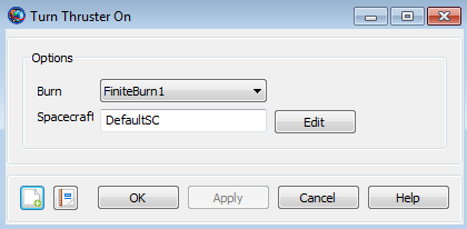
Double-click Turn Thruster On to edit its properties. Notice that the command is already set to apply FiniteBurn1 to the DefaultSC spacecraft, so we don’t need to change anything here.
-
Click OK.
-
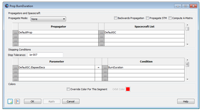
Double-click Prop BurnDuration to edit its properties.
-
We will use the default Parameter value of DefaultSC.ElapsedSecs.
-
Under Condition, replace the default value with Variable, BurnDuration.
-
Click OK to save these changes.
-
Double-click Turn Thruster Off to edit its properties. Notice that the command is already set to end FiniteBurn1 as applied to the DefaultSC spacecraft, so we don’t need to change anything here..
-
Click OK.

-
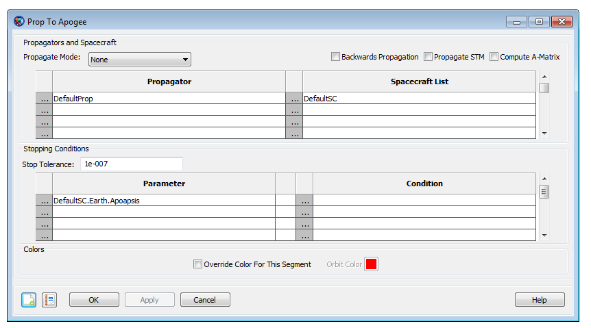
Double-click Prop to Apogee to edit its properties.
-
Under Parameter, replace DefaultSC.ElapsedSecs with DefaultSC.Earth.Apoapsis.
-
Click OK to save these changes.
-
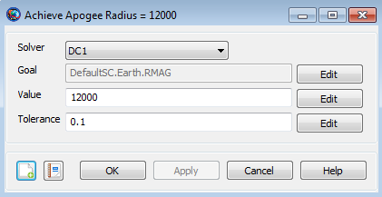
Double-click Achieve Apogee Radius = 12000 to edit its properties.
-
Notice that Goal is set to DefaultSC.Earth.RMAG. This is what we need, so we make no changes here.
-
In the Value box, type
12000 -
Click OK to save these changes
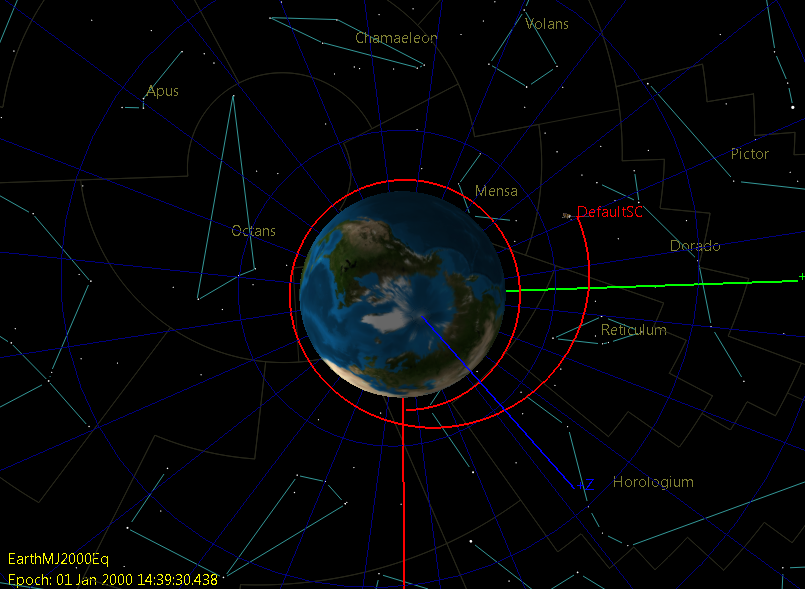
Before running the mission, click Save to save the mission to a file of your choice. Now click Run. As the mission runs, you will see GMAT solve the targeting problem. Each iteration and perturbation is shown in DefaultOrbitView window in light blue, and the final solution is shown in red. After the mission completes, the 3D view should appear as shown in the image shown below. You may want to run the mission several times to see the targeting in progress.
Inspect the 3D DefaultOrbitView window. Manipulate the window as needed to view the orbit "face-on." Visually verify that apogee has indeed been raised.
As shown below, we inspect the output message window to determine the number of iterations it took the DifferentialCorrector to converge and the final value of the control variable, BurnDuration. Verify that you obtained a similar value for BurnDuration.
*** Targeting Completed in 13 iterations

      Final Variable values:

      BurnDuration = 1213.19316329
All of the commands in the Mission tree have associated Command Summary reports. As shown below, we review these reports to help verify that our script performed as expected.
-
In the Mission tree, select Prop To Perigee, then right-click to open the associated Command Summary which describes the state of DefaultSC after the Prop To Perigee command has been performed. We verify perigee has indeed been achieved by finding the mean anomaly value of DefaultSC. To do this, we look at the value of MA under the Keplerian State. As expected, the mean anomaly is zero.
-
View the Turn Thruster On command summary. Note that, as expected, prior to the start of the maneuver, the fuel mass is
756kg. -
View the Turn Thruster Off command summary.
-
Note that the mean anomaly at the end of the maneuver is
25.13degrees. Thus, as the burn occurred, the mean anomaly increased from0to25.13degrees. By orbital theory, we know that an apogee raising burn is best performed at perigee. Thus, we may be able to achieve our orbital goal using less fuel if we “center” the burn. For example, we could try starting our burn at a mean anomaly of–(25.13/2)instead of0degrees. -
Note that, at the end of the maneuver, the fuel mass is
343.76990815648kg. Thus, this finite burn used approximately756 – 343.8=412.2kg of fuel.
-
-
View the Prop To Apogee command summary.
-
We note that the mean anomaly is
180degrees which proves that we are indeed at apogee. -
We note that the orbital radius (RMAG) is
11999.999998192km which proves that we have achieved our desired12000km apogee radius to within our desired tolerance of0.1km.
-