|
Audience |
Beginner |
|
Length |
15 minutes |
|
Prerequisites |
Complete Simulating an Orbit |
|
Script File |
|
In this tutorial, we will use GMAT to perform a finite burn for a spacecraft using an electric propulsion system. Note that targeting and design using electric propulsion is identical to chemical propulsion and we refer you to the tutorial named Target Finite Burn to Raise Apogee for targeting configuration. This tutorial focuses only on configuration and modelling using electric propulsion systems.
The basic steps of this tutorial are:
-
Create and configure the Spacecraft hardware and FiniteBurn Resources
-
Configure the Mission Sequence. To do this, we will
-
Create Begin/End FiniteBurn commands with default settings.
-
Create a Propagate command to propagate while applying thrust from the electric propulsion system.
-
-
Run the mission
For this tutorial, you’ll need GMAT open with the default mission
loaded. To load the default mission, click New
Mission ( ) or start a new GMAT session. We will use the
default configurations for the spacecraft (DefaultSC)
and the propagator (DefaultProp).
DefaultSC is configured by default to a near-circular
orbit, and DefaultProp is configured to use Earth as
the central body with a nonspherical gravity model of degree and order 4.
You may want to open the dialog boxes for these objects and inspect them
more closely as we will leave them at their default settings.
) or start a new GMAT session. We will use the
default configurations for the spacecraft (DefaultSC)
and the propagator (DefaultProp).
DefaultSC is configured by default to a near-circular
orbit, and DefaultProp is configured to use Earth as
the central body with a nonspherical gravity model of degree and order 4.
You may want to open the dialog boxes for these objects and inspect them
more closely as we will leave them at their default settings.
To model thrust and fuel use associated with a finite burn, we must create an ElectricThruster, an ElectricTank, a power system, and then attach the newly created ElectricTank to the ElectricThruster, and attach all hardware to the spacecraft. We'll start by creating the hardware objects.
-
In the Resources tree, right-click on the Hardware folder, point to Add, and click ElectricThruster. A Resource named ElectricThruster1 will be created.
-
In the Resources tree, right-click on the Hardware folder, point to Add, and click ElectricTank. A Resource named ElectricTank1 will be created.
-
In the Resources tree, right-click on the Hardware folder, point to Add, and click SolarPowerSystem. A Resource named SolarPowerSystem1 will be created.
Now we'll configure the hardware models for this exercise.
-
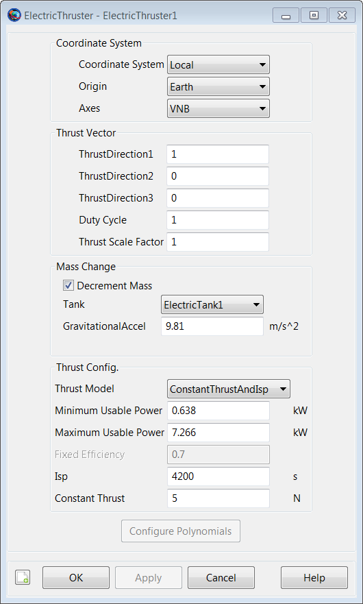
Double-click ElectricThruster1 to edit its properties.
-
In the Mass Change group box, check Decrement Mass.
-
In the Mass Change group box, select ElectricTank1 for the Tank.
-
In the Thrust Config group box, select ConstantThrustAndIsp for ThrustModel and set ConstantThrust to 5.0 N.
Figure 12.1, “ElectricThruster1 Configuration” below shows the ElectricThruster1 configuration that we will use.
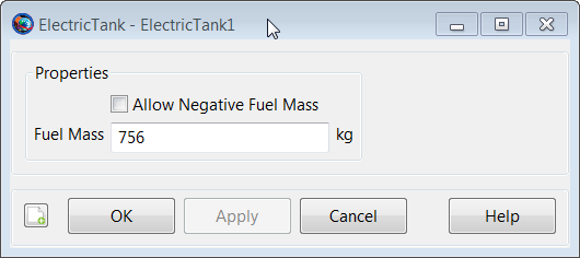
We will use the default tank settings. Figure 12.2, “ElectricTank1 Configuration” shows the finished ElectricTank1 configuration.
-
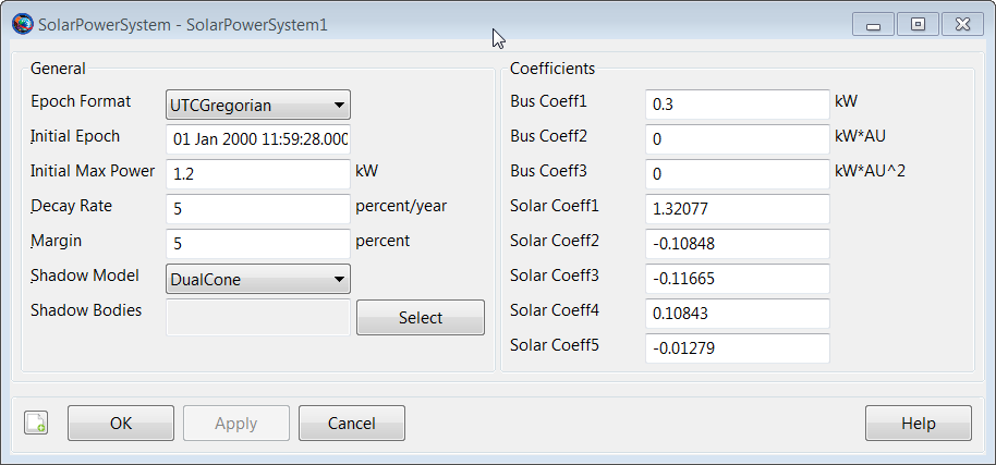
Double-click SolarPowerSystem1 to edit its properties.
-
In the General group box, click the Select button next to ShadowBodies.
-
Remove Earth from the ShadowBodies list.
Figure 12.3, “SolarPowerSystem1 Configuration” shows the finished SolarPowerSystem1 configuration.
-
In the Resources tree, double-click DefaultSC to edit its properties.
-
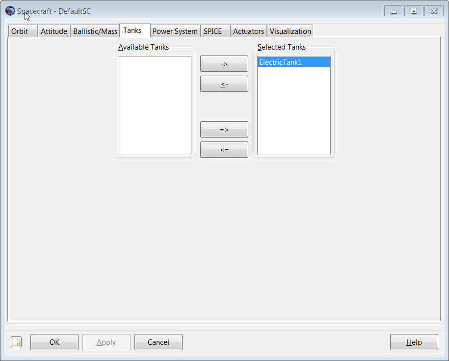
Select the Tanks tab. In the Available Tanks column, select ElectricTank1. Then click the right arrow button to add ElectricTank1 to the SelectedTanks list. Click Apply.
-
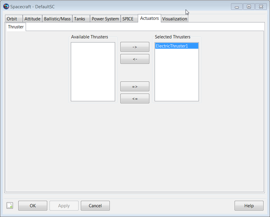
Select the Actuators tab. In the Available Thrusters column, select ElectricThruster1. Then click the right arrow button to add ElectricThruster1 to the SelectedThrusters list. Click OK.
-
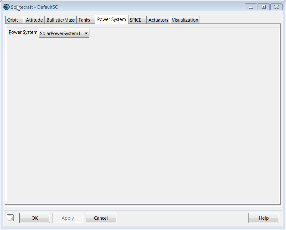
Select the PowerSystem tab. In the PowerSystem tab, select SolarPowerSystem1. Click OK.
We’ll need a single FiniteBurn Resource for this tutorial.
-
In the Resources tree, right-click the Burns folder and add a FiniteBurn. A Resource named FiniteBurn1 will be created.
-
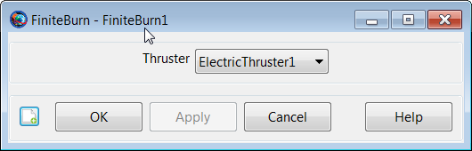
Double-click FiniteBurn1 to edit its properties.
-
Use the menu to the right of the Thruster field to select ElectricThruster1 as the thruster associated with FiniteBurn1. Click OK.
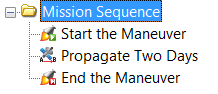
Now we will configure the mission sequence to apply a finite maneuver using electric propulsion for a two day propagation. When we're done, the mission sequence will appear as shown below.
-
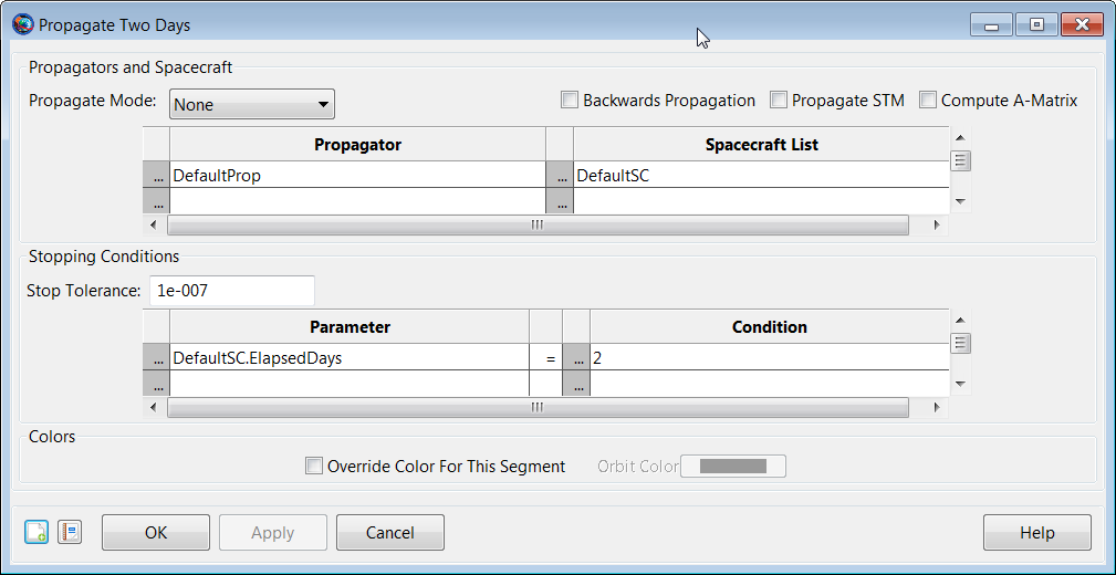
In the Mission Tree, right click on Propagate1, select Rename, and enter Propagate Two Days.
-
Right click on the command named Propagate Two Days, select Insert Before, then select BeginFiniteBurn.
-
Right click on the command named Propagate Two Days, select Insert After, then select EndFiniteBurn.
-
Rename the command named BeginFiniteBurn1 to StartTheManeuver.
-
Rename the command named EndFiniteBurn1 to EndTheManeuver.
Note that for more complex analysis that has multiple FiniteBurn objects, you will need to configure the BeginFiniteBurn and EndFiniteBurn commands to select the desired FiniteBurn Resource. As there is only one FiniteBurn Resource in this example, the system automatically selected the correct FiniteBurn Resource.
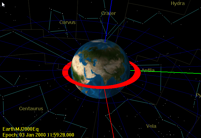
Before running the mission, click Save to save the mission to a file of your choice. Now click Run. As the mission runs, you will see the orbit spiral way from Earth. Note we exaggerated the thrust level so that an appreciable change in the orbit occurs in two days.