Impulse Response (System Identification Toolkit)
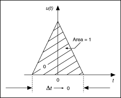
An impulse input, as shown in the following figure, to a dynamic system is defined differently depending on whether the system is discrete or continuous. For a continuous dynamic system, an impulse input, also known as the Dirac delta function, is a unit-area signal with an infinite amplitude and infinitely small duration occurring at a specified time. At all other times, the input signal value is zero. For a discrete system, an impulse is a physical pulse that has unit amplitude at the first sample period and zero amplitude for all other times.

Because the impulse signal excites all frequencies and the duration of this signal is infinitely small, you can see the natural response of the system.
The following figure shows that the impulse response of a linear time-invariant system is equal to the output y(k) of the system when you apply an impulse signal to the input u(k) of the system. The impulse response provides the complete characteristic information of a system.

If you know the impulse response h(n) and the input signal u(k) of a system, then you can compute the output y(k) of the system by using the following equation.

where e(k) is the disturbance of the system.
According to impulse response theory, when you apply a Dirac delta function to a system, the output of the system is the impulse response. You can think of the Dirac delta function δ(x) as a function that has the value of infinity for x = 0, the value zero elsewhere, and a total integral of one. However, generating an ideal Dirac delta function is unrealistic.
If you apply an approximate impulse with a small duration to the input of a system, the output of the system is the approximation of the impulse response of the system. The smaller the duration of the impulse, the closer the output of the system is to the true impulse response. However, an impulse carries little energy and might not excite the system, and noise might corrupt the output of the system. An impulse with a large amplitude and duration can improve the signal-to-noise ratio of the output signal. However, a large amplitude impulse can damage the hardware of the system, and a long-duration impulse leads to inaccuracy. For these reasons, you can use the least squares and correlation analysis methods to estimate the impulse response.
Applications of the Impulse Response
The impulse response not only indicates the stability and causality of the system if feedback exists in the system, but also provides information on properties such as the damping, dominating time constant, and time delay. Some of this information, such as the time delay, is useful for parametric model estimation. Therefore, you can use nonparametric impulse response estimation before parametric model estimation to help estimate the parameters. You can use the SI Estimate Impulse Response VI to estimate the impulse response and determine the time delay of a system by using the correlation analysis method.
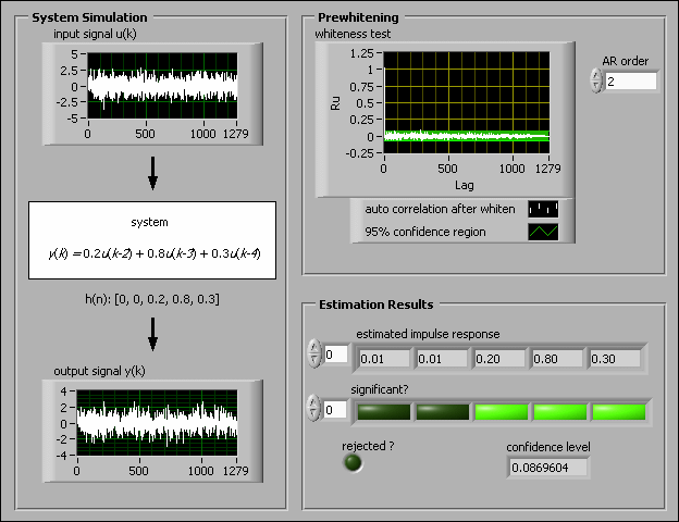
The following figure shows the front panel of a VI that simulates a system defined by the following equation.
y(k) = 0.2u(k – 2) + 0.8u(k – 3) + 0.3u(k – 4)

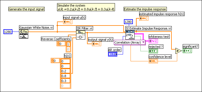
The following figure shows the block diagram of this VI.

In the previous figure, the two initial values of the estimated impulse response are smaller than the confidence level. You can have 99.0% confidence that values less than the confidence level are insignificant, and you can consider those values to be equal to 0. Therefore, you can conclude that the time delay of the system is 2 because the beginning of the first two values of the impulse response are zero.
Another common application of the impulse response is to detect feedback in systems by using the least squares method. If feedback exists in a system, the impulse response of the system becomes significantly large at negative lags and the correlation between the input signal and disturbance e(k) is nonzero. The correlation analysis method assumes the input signal and the disturbance e(k) are independent from each other. Thus, this method cannot estimate accurately the impulse response of the system that contains feedback. Only the least squares method can provide reliable results. You can use the SI Detect Feedback VI to estimate the impulse response of a system and determine whether feedback exists in the system.
Refer to the Feedback Detection VI in the labview\examples\System Identification\Getting Started\General.llb for an example that demonstrates how to use the SI Detect Feedback VI to detect feedback in a system.
