Closed-Loop Systems Model Estimation Methods (System Identification Toolkit)
From LabVIEW System Identification Toolkit
Closed-Loop Systems Model Estimation Methods (System Identification Toolkit)
Systems in many real-world applications contain feedback. Feedback is a process in which the output signal of a plant is passed, or fed back, to the input to regulate the next output. Systems without feedback are open-loop systems. Systems with feedback are closed-loop systems.
In an open-loop system, the stimulus signal and the output noise do not correlate with each other. In a closed-loop system, the stimulus signal correlates to the output noise. Though you can apply many open-loop model estimation methods to closed-loop data, not all open-loop model estimation methods handle the correlation between the stimulus signal and output noise well.
Feedback in Systems
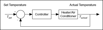
Feedback is common in control systems. With feedback, the system output corresponds to a reference input. Feedback also reduces the effect of input disturbances. One example of a closed-loop system is a system that regulates room temperature, as shown in the following figure. In this example, the reference input is the temperature T set at which you want the room to stay. The thermostat senses the actual temperature, T actual, of the room. Based on the difference between T actual and T set, the thermostat activates the heater or the air conditioner. The thermostat returns T actual as the feedback to compare again with T set. Then the thermostat uses the difference between T actual and T set to regulate the temperature at the next moment.
You must verify if feedback exists before choosing a model estimation method because not all open-loop model estimation methods work correctly with closed-loop data.
| Note You must know whether the data you collect is from an open-loop system or a closed-loop system according to the real-world system configuration. If you do not have such information, you can determine if feedback exists by using the SI Detect Feedback VI or by obtaining the impulse responses of a plant. You can use the Least Squares instances of the SI Estimate Impulse Response VI to estimate the impulse response of a plant. |
The following figure shows a comparison of the impulse responses of the plant in a closed-loop system and an open-loop system.
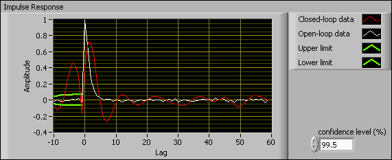
The values outside the upper limit and lower limit range at the negative lag, which appears between –10 and 0 on the x-axis, are considered significant values. Significant values in the impulse response at negative lags imply feedback in data. As shown in the following figure, significant values exist in the Closed-loop data plot. Therefore, feedback exists in the closed-loop system. No significant impulse response values exist in the Open-loop data plot. Thus, feedback does not exist in the open-loop system.
Understanding Closed-Loop Model Estimation Methods
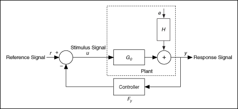
Closed-loop model estimation methods use data from a closed-loop system to build a model for a plant that a controller regulates. The following figure shows a system that consists of a plant and a controller. In this system, G 0 is the plant, F y is the controller, H is the stochastic part of the plant, u is the stimulus signal, y is the response signal, r is the reference signal that is an external signal, and e is the output noise. In control engineering, this system is known as a feedback-path closed-loop system, which is a typical closed-loop system.
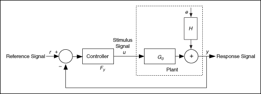
In some cases, the controller comes before the plant in a closed-loop system. This system is known as a feedforward-path closed-loop system, as shown in the following figure.
Depending on the amount of prior knowledge you have about the feedback, the controller, and the reference signal of a system, you can categorize closed-loop model estimation approaches into the following three groups:
- Direct identification—Uses the stimulus and response signals to identify the plant model as if the plant is in an open-loop system. You can apply the direct identification approach to compute all types of models except state-space models by using the LabVIEW System Identification Toolkit.
- Indirect identification—Identifies a closed-loop system by using the reference signal and the response signal and then determines the plant model based on the known controller of the closed-loop system. You can apply the indirect identification approach to compute transfer function models.
- Joint input-output identification—Considers the stimulus signal and the response signal as outputs of a cascaded system. The reference signal and the noise jointly perturb the system, and the plant model is identified from this joint input-output system. You can apply the joint input-output identification approach to compute transfer function models.
You can choose a suitable model identification approach according to the information you have about the closed-loop system. The following table summarizes the information you must have to use each identification approach.
| Stimulus Signal | Response Signal | Reference Signal | Controller Information | |
|---|---|---|---|---|
| Direct | X | X | — | — |
| Indirect | — | X | X | X |
| Joint Input-Output | X | X | X | — |
With the LabVIEW System Identification Toolkit, you can choose to use the direct, indirect, or joint input-output identification approaches for different types of closed-loop systems. The direct identification approach supports single-input single-output (SISO), multiple-input single-output (MISO), and multiple-input multiple-output (MIMO) systems. The indirect and joint input-output identification approaches support SISO systems only.