7 7 1 Create a Relationship
From Visual LANSA Logical Modeler
7.7.1 Create a Relationship
To create a relationship between any two entities, drag-and-drop the Relate connector shape from the Document Stencil onto a blank portion of the model diagram.
Each end of the Relate connector must be attached to an entity. To attach the connector to an entity, drag one end of the connector to the center of the entity that is the source entity in the relationship. Drop the end of the connector when the border of the source entity turns red. If the border of the entity is not red, it will not be attached correctly to the connector. Once you have connected the source entity, drag-and-drop the other end of the connector to the target entity in the same manner.
The source end of the connector is the left-hand end of the connector. The target end of the connector is the right-hand end of the connector.
If you attempt to create an invalid relationship, an error message will be displayed and the connector will be deleted. For example, if you attempt to use an Abstraction in a relationship, an error will occur.
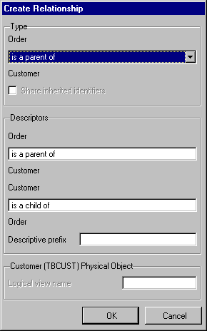
If both ends of the connector have been correctly attached to the entities, the Create Relationship dialog is displayed:
Alternatively, clicking the ![]() button on the main toolbar or selecting the Specify Relationship… option from the Edit pull-down menu will enable you to create a relationship using the following dialog, which is similar to that above:
button on the main toolbar or selecting the Specify Relationship… option from the Edit pull-down menu will enable you to create a relationship using the following dialog, which is similar to that above:
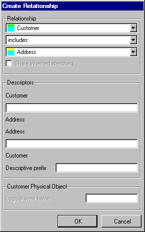
This dialog differs from the one displayed when using the drag-and-drop method in that it lists all available entities in two drop-down lists either side of the relationship type drop-down list. Select the two entities to be related from the drop-down lists.
For either method, the type of relationship being defined between the two entities must be selected. The Type drop-down list will only contain the relationship types that are valid between the two entities. The following table shows which relationships are valid between which entity types:
|
Source Entity Type |
Target Entity Type |
Valid Relationships |
|
Data |
Data |
Parent/Child Mandatory Join Optional Join |
|
Data |
Conceptual |
Includes |
|
Data |
Variant (with no existing Variation relationship) |
Variation |
|
Data |
Variant (with existing Variation relationship) |
Mandatory Join Optional Join |
|
Data |
External |
Mandatory Join Optional Join |
|
Variant |
Data |
Parent/Child Mandatory Join Optional Join |
|
Variant |
Conceptual |
Includes |
|
Variant |
Variant |
Variation |
|
Variant |
External |
Mandatory Join Optional Join |
|
External |
Data |
Parent/Child |
|
External |
Variant |
Variation |
The Share inherited identifiers is used to prevent duplication of the inherited identifying elements. When a relationship is being defined and more than one relationship already exists, then the identifying elements of the source entity can be shared with the target entity. Refer to 1.1.10 Understanding Shared Keys.
Source and Target Descriptors are optionally used to describe the relationship between the two entities from both directions. They are defaulted according to the type of relationship being created, but can be blanked out or overridden with more meaningful descriptions. They serve two functions:
- On the model diagram, the resultant relationship connector, once created, will contain the Source-to-Target description entered here, followed by the Computer Prefix in brackets if it has been specified.
- Descriptions of logical views, access routes and referential integrity validation rules created in the repository will use the text specified here.
A is optional. If specified, it is appended to the start of the element names which are inherited as a result of the relationship. Using a Descriptive prefix helps make the element and resultant field visually unique, as its description is a combination of the computer prefix and the name of the inherited element(s).
Consider this example of Descriptive prefix use:
- The Customer entity has two include relationships with the Address entity: one for delivery address, and one for billing address.
- The descriptive prefix for the first relationship is specified as Delivery. If the Address entity has an element called Zip Code, the field generated in the repository will have a description of Delivery Zip Code.
- The descriptive prefix for the second relationship is specified as Billing. If the Address entity has an element called Zip Code, the field generated in the repository will have a description of Billing Zip Code.
A Logical View Name may be specified if the relationship being created is a join relationship. Note that, if a physical file name of greater than the maximum number of characters allowed (10 if the *RPGIV setting is enabled in your system, 8 if it is not) has been specified for the source entity, a logical view name must be specified before the source entity will successfully build. If, however, a physical file name has been specified that is less than the maximum allowed by two or more characters has been specified, the logical view name is optional. In this instance, the modeler will automatically create a logical view name when the entity is built. This view name will be based on the source entity's physical file and a sequential two digit number.
Note that if an entity inherits the same element multiple times (as with the example above), the field names for the inherited elements must be unique within the inheriting entity. Refer to 6.4.2 Change an Element.
Press the button to create the relationship. Once validation has been passed, the elements inherited by the source or target entity will be shown in the Elements view of the model diagram. In addition, the build status of the entities affected by the relationship will be updated.
Press the button if you do not wish to create the relationship. The Relate connector shape you placed on the diagram will be deleted.
If you are creating more than one relationship between two entities, you should be familiar with 7.7.4 Creating Multiple Relationships.
Reminder: You are not allowed to create a loop structure using parent/child relationships. For example, if entity A is the parent of entity B, then entity B cannot be the parent of entity A. Or, if entity A is the parent of entity B and entity B is the parent of entity C, then entity C cannot be the parent of entity A or B.