Step 2 Relate the Order and Customer Entities
From Visual LANSA Logical Modeler
Step 2. Relate the Order and Customer Entities
In this step, you will create a relationship between the Order and Customer entities and see the impact it has on the Order entity's elements. Our model is based on a classical order processing system where customers place orders for products.
1. Drag the Relate connector from the Document Stencil onto a blank portion of the model diagram.
Note that once dropped, the connector remains as the selected shape, with green handles at each end.
2. Drag-and-drop the Source end handle of the Relate shape (denoted by <- Source) to the centre of the Order entity.
Note that the shape will only be properly connected to the entity when the entity's border turns red.
3. Drag-and-drop the Target end handle of the Relate shape to the centre of the Customer entity. Ensure that the border of Customer turns red before dropping the end of the connector.
If both ends of the connector have been correctly attached, the Create Relationship dialog will be displayed:
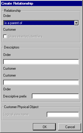
The relationship you are going to create states that an Order must refer to Customer, i.e. an Order cannot exist without referring to an existing Customer.
4. Select 'must refer to' from the Relationship Type drop-down box at the top of the window.
Depending on the types of entity being related, the Relationship Type drop-down list at the top of the window will contain different types of allowable relationships. In this instance, because we are relating two data entities, the allowable relationships are Parent/Child (is a parent of), Mandatory Join (must refer to) and Optional Join (may refer to).
5. The descriptor of a relationship allow the user to specify, in easily understandable terms, the nature of the relationship between the two entities. In this instance, they will be defaulted to 'must refer to' and 'must be referred to by'. Change these to 'is placed by' for the Order/Customer descriptor and 'places an' for the Customer/Order descriptor.
6. Note that the Logical View Name entry field, toward the bottom of the dialog, has been enabled. This is because that, as a result of this join relationship, a logical view for the Order file will be created by the modeler when the model is built. Note that the caption of the box surrounding the entry field has also changed to show to which entity (Order) the logical view name will belong when created. Also shown is the entity's physical file name, to aid you in determining what the logical view name should be called.
Leave the logical view name blank. The impact of this will be shown later.
7. The field names of the inherited elements are important when the entities are built –they must be unique. This will be explained more fully in the following tutorial: LGM004 – Conceptual Entities and the Includes Relationship.
8. Click the button. The model diagram will be updated and the Customer and Order entities will appear something like this:
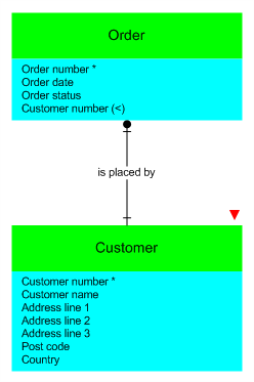
Note the following about the updated diagram:
- The Order entity has inherited the identifying element of Customer Number.
- Order's Customer Number is denoted as being inherited via a join relationship with a lesser than sign in brackets (<).
- The connector between the two entities has had its text set to the Source to Target description that you entered.
- The full impact of the relationship on the two entities will be shown and discussed further in a later tutorial, where these entities will be built.