USB-485 Programmatically Controlled Bias Resistors
From NI Serial Hardware and Software
USB-485 Programmatically Controlled Bias Resistors
On the USB-485 hardware, there are programmatically controlled onboard bias resistors. In addition, the USB-485 two and four-port hardware has user-configurable socketed bias resistors. By default, the USB-485 hardware uses the programmatically controlled bias resistors, which are connected to the receive signals of each port to maintain a known state when the bus is idle. The connections are made as follows:
- RXD+ and CTS– are pulled up to +3.3 V
- RXD– and CTS+ are pulled down to GND
The follwing figure shows a USB transmission line using bias resistors.
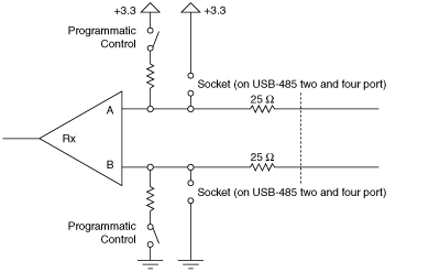
USB-485 Transmission Line Using Bias Resistors
The values of the programmatically controlled bias resistors have been calculated such that there is a voltage of at least 200 mV between the differential pair. Rather than using the programmatically controlled bias resistors, you can load custom values of resistors into the sockets in front of each connector or use external bias resistors. If these resistors are installed, make sure the programmatically controlled bias resistors are disabled.
| Note Using custom bias resistors on the USB-485 two port may violate the USB suspend current specification. |
|
Note The series 25 |