Bias Resistors
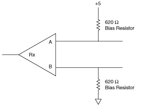
An RS-485 transmission line enters an indeterminate state if no nodes are transmitting on it. This indeterminate state can cause the receivers to receive invalid data bits from noise picked up on the cable. To prevent a line from receiving these data bits, the transmission line can be forced into a known state by installing two bias resistors at one node on the transmission line. Doing so creates a voltage divider that forces the voltage between the differential pair to be greater than 200 mV, the threshold voltage for the receiver.
The following figure shows a transmission line using bias resistors.

Transmission Line Using Bias Resistors
On the PCI RS-485 two and four-port serial cards, PXI RS-485 two and four-port serial cards, and ENET RS-485 two and four-port serial cards, there are four user-configurable bias resistors in front of each connector. These resistors are socketed and pre-loaded with 620  resistors. They are connected to the receive signals of each port to maintain a known state when the bus is idle. The connections are made as follows:
- RXD+ and CTS– are pulled up to +5 V
- RXD– and CTS+ are pulled down to GND
Rather than using two 620  resistors at one node, you can increase the value of the resistors and put them at every node. For instance, if there are eight nodes in a system, you can use 4.7 k
 resistors at each node to effectively achieve the same result.
 is available.