Patch Clamp Amplifier Settings
From WinFluor V4.0.3
Recording > Signals Monitor (Seal Test) > Patch Clamp Amplifier Settings
The patch clamp current gain (in voltage-clamp mode) and voltage gain (current-clamp mode) is indicated in the Amplifier group box.
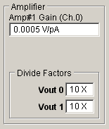
When using a patch clamp with gain telegraph support the Gain value is automatically updated when the gain setting is changed on the patch clamp front panel.
The voltage output channel (Vout 0 or Vout 1) connected to the patch clamp command voltage input is displayed in the V Command O/P to list. The patch clamp command voltage division factor used to scale the stimulus voltage output to obtain the correct voltage at the cell is indicated in the Divide Factor box.
The Gain, O/P to and Divide Factor settings are set automatically, when a specific amplifier supported by WinFluor (e.g.Amplifier = Axopatch 1D, Axopatch 200 etc.) has been selected as the Amplifier in in Setup Patch Clamp/Analogue Inputs dialog box. When an unsupported amplifier is in used (Amplifier = None or Manual Gain Entry) appropriate settings must be entered by user.