Stimulus Outputs
From WinFluor V4.0.3
Getting Started > Stimulus Outputs
WinFluor can generate analog or digital stimulus waveforms simultaneously with image and analogue signal recording. If sufficient output channels are available, up to 3 voltage stimulus waveform output channels and TTL digital pulse output channels can be supported.
Stimulus output channels are configured on the Stimulus Outputs setup page..
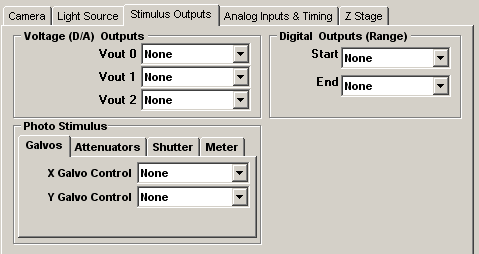
Voltage (D/A) Outputs
To select an analogue output channel for voltage stimulus waveform #0, select a DAC channel from the Vout 0 list, or select None to disable it. (Note. When a patch clamp is in use, Vout 0 is typically used to provide the command voltage signal.)
To select an analogue output channel for Voltage stimulus waveforms #1 or #2, select a DAC channel from the Vout 1 or Vout 2 list, or select None to disable it.
Digital Outputs
To select a range of digital pulse stimulus channels, select the first digital output line from the Digital Outputs (Range) Start list and the last digital output from the End list, or select None to disable digital outputs.
Photo Stimulus
The Photo Stimulus settings configure WinFluor's laser stimulated point photolysis feature (currently only available when used with Prairie Technology Ultima microscope).
Galvos
Select the analog outputs used to control laser position from the X and Y Galvo Control list boxes.
Attenuators
Select the analog outputs used to control laser attenuators (Pockel Cells) from the Attenuator Control Channels 1-3 list boxes.
Shutter
Select the analog outputs used to control laser safety shutter from the Shutter Control Channel 1 . Enter the shutter opening time into the Latency field and select whether the shutter is opened by an 5V signal level (Active High) or 0V (Active Low).
Meter
Select the signal level meter from Meter Input list box.