Creating Stimulus Protocols
From WinFluor V4.0.3
Stimulus Protocols > Creating Stimulus Protocols
Stimulus protocols can consist of voltage waveforms on up to 3 voltage output channels ( Vout 0-2) and 5V TTL digital waveforms on up to 8 TTL digital output channels (Note. Number of available DAC and digital channels depends on laboratory interface type and available output lines).
To create a new (or edit an existing) stimulus protocol file, select
Setup Stimulus Protocol Editor
to open the stimulus protocol editor. A diagram of the output waveforms appears in the Waveform display box.
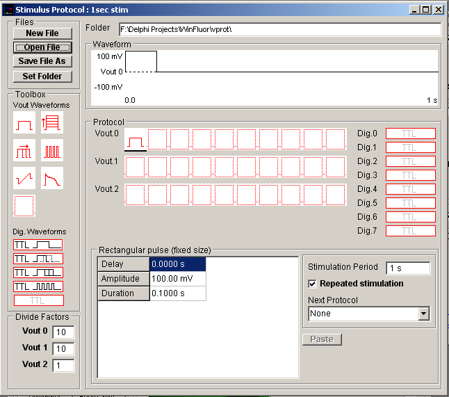
To begin, click the New File button to create a blank protocol or Open File to load an existing protocol.
Voltage waveform stimuli
Voltage waveforms are constructed by dragging Vout waveform elements from the Toolbox
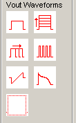
and dropping them into the selected Vout.0, Vout.1 or Vout.2 voltage waveform sequence within the protocol.

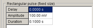
A voltage waveform can consist of a sequence of up 10 separate waveform elements. The amplitude and duration for each element is defined in its parameters table which can be made to appear by clicking the element in the waveform sequence.
Seven different waveform elements are available (rectangular pulse; family of pulses incrementing in amplitude; family of pulses incrementing in duration; train of pulses; series of pulse trains, varying in frequency; ramp; user-defined waveform) Details of each waveform shape and its parameters are defined in Table ?.1
Digital stimulus waveforms
To create a digital stimulus waveform, drag a digital stimulus element from the Toolbox
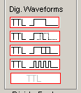
and drop it into the selected digital output channel.
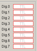
Each digital output channel controls the on (5V) / off (0V) state of a digital output line. The duration and inverted/non-inverted signal polarity for each protocol is defined in its parameters table which can be made to appear by clicking on the element in the protocol list
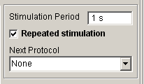
Repeated and linked protocols
Waveform protocols can be made to repeat by ticking the Repeated Stimulation option and entering a repetition time in the Stimulation Period box. Multiple stimulus protocols can also be linked together by selecting the name of another protocol in the Next Protocol list (When linked protocols are in use, the time set in Stimulation Period determines the time interval between protocols).
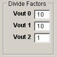
Divide factors
Most voltage and patch clamp amplifiers divide down their command voltage input signals by some factor. Enter the scaling factor into the Divide Factor box. This factor is used to scale the stimulus voltage output to the voltage output channel to obtain the correct voltage at the cell. (NOTE. The voltage divide factors for Vout 0 and Vout 1 set automatically when amplifiers supported by WinFluor have been selected as Amplifiers #1 and #2.)
Saving a stimulus protocol
On completion, a stimulus protocol can be saved for use, by clicking the Save File As button and providing a name for the protocol file.
Stimulus protocol folder
Protocol files are stored in the folder c:\winfluor\vprot (the default location) and appear in the stimulus protocols list in the live recording window. To change the folder used to store protocol files, click the Set Folder button to open the folder selection dialog box and create or select another folder.