Excitation Wavelength Sequences
From WinFluor V4.0.3
Recording > Images + Signals > Excitation Wavelength Sequences
The excitation/emission light editor allows up to 20 fluorescence excitation/emission wavelength combinations to be defined for selection by the Excitation Light control in the Record Image and Record Images & Signals windows. Excitation/emission wavelength sequences of up to 9 of these wavelengths can be defined and applied sequentially. (A multi-wavelength fluorescent light source is required (monochromator, LED, filter wheel) for excitation wavelength control and and filter wheel in the emission light path for emission light bandwidth control.)
To configure the light wavelengths and sequences select
SetupExcitation Light Wavelengths
to display the Excitation Light Setup dialog box.
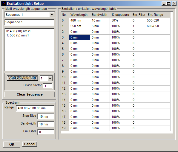
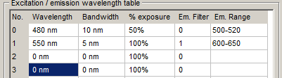
Excitation/Emission Wavelengths Table
The excitation/emission wavelengths table defines up to 20 excitation/emission light wavelength combinations.
Wavelength/Bandwidth: For monochromators, the Wavelength column defines the centre wavelength (nm) of the excitation light passband and the Bandwidth column the width (nm) of the passband. (Note. The Bandwidth setting is ignore by monochromators without digitally controllable slit width.) For fixed wavelength light sources (filter wheels, LEDS), filters are selected by row number and the centre wavelength and bandwidth of the filter/LED associated with each row should be entered in the Wavelength and Bandwidth columns.
% Exposure: The % Exposure column allows the camera exposure time (expressed as a % of the camera exposure interval, selected in a recording window) to be varied for different wavelength combinations, allowing high and low level fluorescence images to be captured within a single sequence without overloading the camera. Reducing % Exposure from its default value of 100% reduces the fraction of time during the exposure interval when the camera is being exposed. (Note. Bulb exposure mode must be enabled in the Camera/System Setup page for % exposure settings to take effect. Only Photometrics PVCAM cameras currently support this option.)
Em Filter/Em Range: The Em Filter column, selects the index number of the emission filter (0 - (No. Filters-1)) to be used by the filter combination. (If an emission filter is not available, this entry is ignored). The passband of the emission filter is entered in to the Em Range column. This is added to the image panel labels in the recording windows.
Multi-wavelength Sequence:
The multi-wavelength sequence list defines a series of up to 9 wavelengths selected from the wavelength table which can be applied in a cyclic sequence at either of two rates when the multi-wavelength excitation option is selected within the Record Images window. Up to 10 sequences can be defined and each given a specific name.
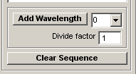
To define a wavelength sequence, click Clear Sequence to clear the wavelength sequence list. Select the row number of a wavelength from the Excitation Wavelength table then click the Add Wavelength button.
The value in the Divide factor box for each wavelength determines the rate at which it is applied within the sequence. When all wavelengths have a divide factor of 1 (or the same divide factor) a simple cycle of the wavelengths within the sequence is produced. When a divide factor of N (N>1) is applied to one or more of the wavelengths, these wavelengths are applied at 1/N the rate of the others. For instance, a sequence of 3 wavelengths (0,1,2) where 0 has a divide factor of 5 and the rest 1.
0: 480(10) nm /5
1: 340(10) nm /1
2: 380(10) nm /1
produces the sequence
0 1 2 1 2 1 2 1 2 1 2 0 1 2 1 2 1 2 1 2 1 2 …
Note. Only two divide factor values are allowed with a sequence, one of which must be 1, the other less than 100. Those wavelengths with a divide factor greater than one are always placed at the beginning of the sequence.
Spectrum
The spectrum options define the spectral sequence applied when the Spectrum excitation option is selected in the Live Images window.
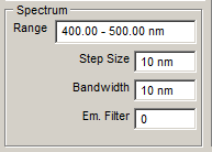
To define a spectral sequence, enter the beginning and end (in nm) of the range of wavelengths to be applied into the Range box.
Enter the amount (in nm) that the wavelength is to be shifted after each frame is acquired in the Step Size box. Enter the width (in nm) of the passband to be used in the Bandwidth box.
Select the emission filter to be used in the Em Filter box (ignored if no emission filter is available).