Cortex Microcontroller Software Interface Standard
SPI Device
This file describes the SPI Device Driver for Cortex Microcontroller Software Interface Standard (CMSIS).
Version: 1.10 - 24. February 2009
Information in this file, the accompany manuals, and software is
Copyright © ARM Ltd.
All rights reserved.
Revision History
- Revision 0.01 - February 2009: Concept
- Revision 1.10 - February 2009: First Release
Contents
- About
- CMSIS Spi Device Files
- CMSIS Spi Device Definitions
- CMSIS Spi Device I/O Block
- CMSIS Spi Device Functions
- Flowcharts
About
The CMSIS Spi Device provides a standard interface to a Serial peripheral interface (SPI) that is part of a Cortex-M3 system. This interface is an hardware abstraction layer for the SPI. It consists of a general Spi Device Driver (files SpiDev.h) and a device specific Spi Device Driver (files SpiDev_STM32.[h,c]). The device specific Spi Device Driver provides an I/O Block to pass parameter and to access the Device Driver. Each Spi Device needs a device specific Spi Device Driver which provides it's own I/O block.
To ease use and design of the Spi Device Driver only one SPI can be used, Data Frame Format is limited to 8 bit and only master mode is possible. This will cover most of the use cases for a SPI.
CMSIS Spi Device Files
The sample driver is implemented for a ST Microlectronics STM32F103 device and uses the following files:
| Name | Description |
|---|---|
| SpiDev.h | Global defines and structure definitions for general Spi Device interface. |
| SpiDev_STM32.h | Device dependent definitions of the device specific Spi Device Driver. |
| SpiDev_STM32.c | Device specific Spi Device Driver. |
File SpiDev.h
| Description | File SpiDev.h contains function prototypes and type definitions for configuration values. Also global defines are part of this file. File SpiDev.h must be included in the application. This file contains the type definition for I/O Block. The I/O block contains configuration values and function pointer to access the device specific Spi Device Driver . |
File SpiDev_STM32.h
| Description | File SpiDev_STM32.h contains STM32F103 device specific defines like registers and register values. It is only included from file SpiDev_STM32.c. |
File SpiDev_STM32.c
| Description | File SpiDev_STM32.c contains static functions of this specific Spi Device Driver and provides the Device Driver specific I/O block. It must be linked to the application. The compiler switches _SPI_, _SPI_REMAP_are used to select the SPI and the SPI pins. |
| Compiler switches |
_SPI_
_SPI_REMAP_
|
CMSIS SPI Device Definitions
Spi Device Driver uses following definitions for configuartion and function parameter values:
| Name | Description |
|---|---|
| Global Defines | Global defined values. |
| Spi Configuration | Spi Configuration parameters. |
Global Defines
| Summary |
#define SpiDev_CLOCK_POLARITY_IDLELOW 0 #define SpiDev_CLOCK_POLARITY_IDLEHIGH 1 #define SpiDev_CLOCK_PHASE_FIRSTEDGE 0 #define SpiDev_CLOCK_PHASE_SECONDEDGE 1 #define SpiDev_SSO_DISABLED 0 #define SpiDev_SSO_ENABLED 1 |
| Description |
These defines are used from the Spi Device Driver. |
| Define |
SpiDev_CLOCK_POLARITY_IDLELOW SpiDev_CLOCK_POLARITY_IDLEHIGH SpiDev_CLOCK_PHASE_FIRSTEDGE SpiDev_CLOCK_PHASE_SECONDEDGE SpiDev_SSO_DISABLED SpiDev_SSO_ENABLED |
Spi Configuration
| Summary |
typedef struct {
   uint32_t Baudrate:25;
   uint32_t Polarity:1;
   uint32_t Phase:1;
   uint32_t SlaveSelect:1;
   uint32_t Reserved:4;
} SpiDev_CFG;
|
| Description |
Spi Configuration attributes and explanation. |
| Attributes |
BaudRate Polarity
Phase
SlaveSelect
Reserved |
CMSIS Spi Device I/O Block
Spi Device Driver defines the following structure to pass initialization data and to access device specific functions:
| Name | Description |
|---|---|
| SpiDev_IOB | Structure for configuration values and functions pointers to the Spi Device Driver. |
Structure SpiDev_IOB
| Summary |
typedef struct {
   SpiDev_CFG   Cfg;
   int (*Init)       (void);
   int (*UnInit)     (void);
   int (*BufTxRx)    (void *pDataTx, void *pDataRx, unsigned int Size);
   int (*SetBaudrate)(unsigned int Baudrate);
} SpiDev_IOB;
|
| Description |
This structure is used to hold configuration values and function pointers to access the device specific Spi Device Driver. The configuration values are preset with default values. |
| Attributes |
Cfg int (*Init) (void); int (*UnInit) (void); int (*BufTxRx) (void *pDataTx, void *pDataRx, unsigned int Size); int (*SetBaudrate)(unsigned int Baudrate); |
CMSIS Spi Device Functions
Spi Device Driver contains the following static functions:
| Name | Description |
|---|---|
| SpiDev_Init | Initialize and start the Spi Device Driver. |
| SpiDev_UnInit | Uninitialize and stop the Spi Device Driver. |
| SpiDev_BufTxRx | Pass data to the Spi Device Driver to transmit and return received data. |
| SpiDev_SetBaudrate | Change used Baudrate. |
Function SpiDev_Init
| Summary |
static int SpiDev_Init (void); |
| Description | This function initializes the Spi Device Driver according the SpiDev_IOB structure and starts it. |
| Parameter | none |
| Return Code |
|
Function SpiDev_UnInit
| Summary |
static int SpiDev_UnInit (void); |
| Description | This function uninitializes the Spi Device Driver and stops it. |
| Parameter | none |
| Return Code |
|
Function SpiDev_BufTxRx
| Summary |
static int SpiDev_BufTxRx (void *pDataTx, void *pDataRx, unsigned int Size); |
| Description | This function passes data to the specific Spi Device Driver to transmit. It returns also the received data. This function is blocking. |
| Parameter |
pDataTx pDataRx Size |
| Return Code |
|
Function SpiDev_SetBaudrate
| Summary |
static int SpiDev_SetBaudrate(unsigned int Baudrate); |
| Description | This function changes the currently used Baudrate. If it is not possible to use the specified Baudrate then the next lower possible Baudrate is used. |
| Parameter |
Baudrate |
| Return Code |
|
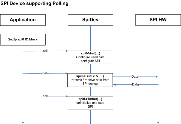
Flowcharts
The following Flowchart shows a typical Spi Device flow.