| AttrId specifies the attribute to set.
Baud Rate
For NI CAN hardware you can specify the following basic baud rates as the numeric rate: 5000, 6150, 7813, 8000, 10000, 12500, 15625, 16000, 20000, 25000, 31250, 33333, 40000, 50000, 62500, 80000, 83333, 100000, 125000, 160000, 200000, 250000, 400000, 500000, 800000, and 1000000.
You can specify advanced baud rates as 8000XXYY hex, where YY is the value of Bit Timing Register 0 (BTR0), and XX is the value of Bit Timing Register 1 (BTR1) of the SJA1000 CAN controller.
For NI LIN hardware you can specify any baud rate from 2400 to 20000 baud. If the baud rate you select varies more than .5% from the calculated baud rate, you will receive a warning message. The calculation for the baud rate is as follows:
Calculated Baud Rate = 1,500,000/x
where x = (1,500,000/Input Baud Rate), rounded to the nearest integer.
LIN Checksum Type
Specifies the method the LIN interface should use when calculating checksums for published data, or verifying received checksums for subscribed-to data. The values for this attribute are:

| 0 |
Classic (default) |
| 1 |
Enhanced |
Setting the LIN Checksum Type to Classic indicates that the LIN-specified checksum calculation algorithm should be applied only to the data bytes. Setting the LIN Checksum Type to Enhanced indicates that the checksum calculation algorithm should be applied to the ID and data bytes.
LIN Enable DLC Check
Specifies the manner in which the LIN interface detects end-of-response when writing a header IsRemote type. This attribute does not affect the LIN interface processing of the full and response IsRemote types. The values for this attribute are:
When the LIN interface transmits a header, it expects an external slave to publish data in response. When writing headers, the LIN interface detects end-of-response using either the LIN-specified response timeout for a response containing the maximum number (8) of data bytes (LIN Enable DLC Check=FALSE), or reception of a response containing DLC number of data bytes (LIN Enable DLC Check=TRUE). If LIN Enable DLC Check=FALSE, then the minimum time separation between the transmission of headers will be header time + time to subscribe to eight data bytes (DLC is ignored) and checksum + LIN interface inter-frame delay. If LIN Enable DLC Check=TRUE, then the minimum time separation between the transmission of headers will be header time + time to subscribe to DLC number of data bytes and checksum + LIN interface inter-frame delay.
If you want to transmit header frames, each separated by a unique schedule table amount of delay with maximum timing accuracy, set LIN Enable DLC Check to TRUE. Note that if LIN Enable DLC Check=TRUE, the LIN interface will verify that a DLC in the range of one to eight is in the header IsRemote type written by the host. If LIN Enable DLC Check=FALSE, the LIN interface will ignore the DLC in the header IsRemote type written by the host.
LIN Log Wakeup
Specifies whether the LIN interface should report wakeup events as frames (TRUE) or not (FALSE). Wakeup events are always reported as states. The values for this attribute are:
LIN Response Timeout
Specifies an amount of response timeout, in 50 µs increments, to add to the LIN-specified response timeout the LIN interface uses to detect certain bus errors and end-of-response. The values for this attribute are:
| 0 |
(default) |
| 1 |
1 to 65535 (50 µs increments to add to LIN-specified response timeout) |
LIN Sleep
Sets the sleep state of the LIN interface. The values for this attribute are:
The LIN interface powers up in the awake state (LIN Sleep=FALSE). When the LIN Sleep attribute is set to FALSE, the user may set it to TRUE at any time: upon reception of a sleep frame (four second period of bus inactivity has passed), upon reception of a full frame containing go-to-sleep command data, or when it is desired to simply put the interface to sleep. When the LIN Sleep attribute is set to TRUE, either the user or the state machines within the LIN interface may set the attribute to FALSE, depending upon whether the interface is acting as master or slave, and whether or not it is issuing or receiving the wakeup request.
Listen Only?
Specifies whether to use the listen only feature of the Philips SJA1000 CAN controller (Series 2 only).
Communication must be stopped to set this attribute. Use Start On Open False with ncConfigCANNet, set the attribute, then use ncAction to start communication.
0 (FALSE)
When set to FALSE, listen only mode is disabled (default).
Received frames are ACKnowledged, and frames can be transmitted using ncWriteNet and ncWriteObj.
1 (TRUE)
When set to TRUE, listen only mode is enabled.
The Network Interface and CAN Objects can only receive frames. The interface does not transmit on the network: no
ACKnowledgements are transmitted for received frames, and ncWriteNet and ncWriteObj will return an error. The Philips SJA1000 CAN controller enters error passive state when listen only is enabled.
The listen only mode is not available on the Intel 82527 CAN controller used by Series 1 CAN hardware (returns error).
This attribute is available only for the Network Interface, not CAN Objects.
Log Bus Errors?
Specifies whether to log bus errors when the interface detects a bus error. For CAN interfaces, the bus error frame is logged when a bus error is detected. The Log Bus Error? attribute is not supported by Series 1 CAN interfaces. This attribute has to be set prior to starting the Network Interface. The values for this attribute are:
| 0 |
FALSE (default)
When set to FALSE, bus errors will not be logged and cannot be read (default).
|
| 1 |
TRUE
When set to TRUE, the Network Interface reports bus errors as a special frame in the read queue. For CAN, if the Log Comm Warnings? attribute is set to 1 (TRUE), the Log Bus Errors? attribute must be set to 0 (FALSE).
|
The CAN bus error frame has the following format:
| Timestamp |
Time when the bus error was detected. |
| Arbitration ID |
0 |
| IsRemote |
6 |
| DataLength |
4 |
| Data |
Bytes
0–Comm State (see description below)
1–Transmit Error Counter
2–Receive Error Counter
3–ECC Register
4–X
5–X
6–X
7–X
Note: X means Reserved or Don't Care.
The first data byte (Comm State) indicates the current communication state of the CAN controller. The states are:
0–Error Active
1–Error Passive
2–Bus Off
|
For LIN interfaces, the bus error frame is logged into the read queue when a timeout or bus errors such as Bit Framing or Checksum occurs. This attribute must be set prior to starting the Network Interface.
The LIN bus error frame has the following format:
| Timestamp |
Time when the bus error was detected. |
| Arbitration ID |
0 |
| IsRemote |
21 |
| DataLength |
4-7 (depends on Error code) |
| Data |
Bytes
0–Error code (most significant byte)
1–Error code (least significant byte)
2–X
3–X
4–Received byte (for applicable error code)
5–Expected byte (for applicable error code)
6–LIN ID (for applicable error code)
7–X
Note: X means Reserved or Don't Care.
|
Data bytes zero and one (Error code) indicate the type of LIN bus error. Refer to the following table for a list of LIN bus error codes and descriptions. Data bytes two and three are reserved for internal use. For errors in which a received byte did not match the expected value, data byte four indicates the received value and data byte 5 indicates the expected value. For a bus error occurring at a point in the LIN frame after which the break, sync, and ID fields have been processed, data byte six indicates the LIN ID.
 |
Note In the table below, X means Reserved. |
| Error Name |
Error Code (hex) |
Description |
Frame Contents |
| DLC |
B(0) |
B(1) |
B(2) |
B(3) |
B(4) |
B(5) |
B(6) |
| LinBusErrorNoResponse |
8400 |
The LIN interface slave task received a header but no response. |
7 |
84 |
00 |
X |
X |
0 |
0 |
ID |
| LinBusErrorResponseTooShort |
8401 |
The LIN interface slave task received a header and only one byte of a response. |
7 |
84 |
01 |
X |
X |
0 |
0 |
ID |
| LinBusErrorRxChecksumBit |
C008 |
The LIN interface slave task received a checksum byte with a bit error. |
7 |
C0 |
08 |
X |
X |
Received Checksum Byte |
Expected Checksum Byte |
ID |
| LinBusErrorRxChecksumFraming |
A008 |
The LIN interface slave task received a checksum byte with a framing error. |
7 |
A0 |
08 |
X |
X |
0 |
0 |
ID |
| LinBusErrorRxData0Framing |
A010 |
The LIN interface slave task received data byte 0 with a framing error. |
7 |
A0 |
10 |
X |
X |
0 |
0 |
ID |
| LinBusErrorRxData1Framing |
A011 |
The LIN interface slave task received data byte 1 with a framing error. |
7 |
A0 |
11 |
X |
X |
0 |
0 |
ID |
| LinBusErrorRxData2Framing |
A012 |
The LIN interface slave task received data byte 2 with a framing error. |
7 |
A0 |
12 |
X |
X |
0 |
0 |
ID |
| LinBusErrorRxData3Framing |
A013 |
The LIN interface slave task received data byte 3 with a framing error. |
7 |
A0 |
13 |
X |
X |
0 |
0 |
ID |
| LinBusErrorRxData4Framing |
A014 |
The LIN interface slave task received data byte 4 with a framing error. |
7 |
A0 |
14 |
X |
X |
0 |
0 |
ID |
| LinBusErrorRxData5Framing |
A015 |
The LIN interface slave task received data byte 5 with a framing error. |
7 |
A0 |
15 |
X |
X |
0 |
0 |
ID |
| LinBusErrorRxData6Framing |
A016 |
The LIN interface slave task received data byte 6 with a framing error. |
7 |
A0 |
16 |
X |
X |
0 |
0 |
ID |
| LinBusErrorRxData7Framing |
A017 |
The LIN interface slave task received data byte 7 with a framing error. |
7 |
A0 |
17 |
X |
X |
0 |
0 |
ID |
| LinBusErrorRxIdFraming |
A020 |
The LIN interface slave task received an ID byte with a framing error. |
6 |
A0 |
20 |
X |
X |
Received ID Byte |
Expected ID Byte |
N/A |
| LinBusErrorRxIdParity |
C020 |
The LIN interface slave task received an ID byte with a parity error. |
6 |
C0 |
20 |
X |
X |
Received ID Byte |
Expected ID Byte |
N/A |
| LinBusErrorRxIdTimeout |
9020 |
The LIN interface slave task did not receive an ID byte within the header timeout period. |
4 |
90 |
20 |
X |
X |
N/A |
N/A |
N/A |
| LinBusErrorRxSyncBit |
C040 |
The LIN interface slave task received a sync byte with a bit error. |
6 |
C0 |
40 |
X |
X |
Received Sync Byte |
Expected Sync Byte |
N/A |
| LinBusErrorRxSyncFraming |
A040 |
The LIN interface slave task received a sync byte with a framing error. |
4 |
A0 |
40 |
X |
X |
N/A |
N/A |
N/A |
| LinBusErrorRxSyncTimeout |
9040 |
The LIN interface slave task did not receive a sync byte within the header timeout period. |
4 |
90 |
40 |
X |
X |
N/A |
N/A |
N/A |
| LinBusErrorTxData0Bit |
4010 |
The LIN interface slave task transmitted data byte 0 and self-received it with a bit error. |
7 |
40 |
10 |
X |
X |
Received Data Byte |
Expected Data Byte |
ID |
| LinBusErrorTxData1Bit |
4011 |
The LIN interface slave task transmitted data byte 1 and self-received it with a bit error. |
7 |
40 |
11 |
X |
X |
Received Data Byte |
Expected Data Byte |
ID |
| LinBusErrorTxData2Bit |
4012 |
The LIN interface slave task transmitted data byte 2 and self-received it with a bit error. |
7 |
40 |
12 |
X |
X |
Received Data Byte |
Expected Data Byte |
ID |
| LinBusErrorTxData3Bit |
4013 |
The LIN interface slave task transmitted data byte 3 and self-received it with a bit error. |
7 |
40 |
13 |
X |
X |
Received Data Byte |
Expected Data Byte |
ID |
| LinBusErrorTxData4Bit |
4014 |
The LIN interface slave task transmitted data byte 4 and self-received it with a bit error. |
7 |
40 |
14 |
X |
X |
Received Data Byte |
Expected Data Byte |
ID |
| LinBusErrorTxData5Bit |
4015 |
The LIN interface slave task transmitted data byte 5 and self-received it with a bit error. |
7 |
40 |
15 |
X |
X |
Received Data Byte |
Expected Data Byte |
ID |
| LinBusErrorTxData6Bit |
4016 |
The LIN interface slave task transmitted data byte 6 and self-received it with a bit error. |
7 |
40 |
16 |
X |
X |
Received Data Byte |
Expected Data Byte |
ID |
| LinBusErrorTxData7Bit |
4017 |
The LIN interface slave task transmitted data byte 7 and self-received it with a bit error. |
7 |
40 |
17 |
X |
X |
Received Data Byte |
Expected Data Byte |
ID |
| LinBusErrorTxData0Framing |
2010 |
The LIN interface slave task transmitted data byte 0 and self-received it with a framing error. |
7 |
20 |
10 |
X |
X |
0 |
0 |
ID |
| LinBusErrorTxData1Framing |
2011 |
The LIN interface slave task transmitted data byte 1 and self-received it with a framing error. |
7 |
20 |
11 |
X |
X |
0 |
0 |
ID |
| LinBusErrorTxData2Framing |
2012 |
The LIN interface slave task transmitted data byte 2 and self-received it with a framing error. |
7 |
20 |
12 |
X |
X |
0 |
0 |
ID |
| LinBusErrorTxData3Framing |
2013 |
The LIN interface slave task transmitted data byte 3 and self-received it with a framing error. |
7 |
20 |
13 |
X |
X |
0 |
0 |
ID |
| LinBusErrorTxData4Framing |
2014 |
The LIN interface slave task transmitted data byte 4 and self-received it with a framing error. |
7 |
20 |
14 |
X |
X |
0 |
0 |
ID |
| LinBusErrorTxData5Framing |
2015 |
The LIN interface slave task transmitted data byte 5 and self-received it with a framing error. |
7 |
20 |
15 |
X |
X |
0 |
0 |
ID |
| LinBusErrorTxData6Framing |
2016 |
The LIN interface slave task transmitted data byte 6 and self-received it with a framing error. |
7 |
20 |
16 |
X |
X |
0 |
0 |
ID |
| LinBusErrorTxData7Framing |
2017 |
The LIN interface slave task transmitted data byte 7 and self-received it with a framing error. |
7 |
20 |
17 |
X |
X |
0 |
0 |
ID |
| LinBusErrorTxChecksumBit |
4008 |
The LIN interface slave task transmitted a checksum and self-received it with a bit error. |
7 |
40 |
08 |
X |
X |
Received Checksum Byte |
Expected Checksum Byte |
ID |
| LinBusErrorTxChecksumFraming |
2008 |
The LIN interface slave task transmitted a checksum and self-received it with a framing error. |
7 |
20 |
08 |
X |
X |
0 |
0 |
ID |
| LinBusErrorErrorWhenMasterReceivesWakeup |
8A00 |
The LIN interface as a master, failed to respond to reception of a wakeup on the LIN. |
4 |
8A |
00 |
X |
X |
N/A |
N/A |
N/A |
| LinBusErrorWhenMasterIssuesWakeup |
0A00 |
The LIN interface failed to issue a wakeup on the LIN as a master. |
4 |
0A |
00 |
X |
X |
N/A |
N/A |
N/A |
| LinBusErrorWhenSlaveIssuesWakeup |
900 |
The LIN interface failed to issue a wakeup on the LIN as a slave. |
4 |
09 |
00 |
X |
X |
N/A |
N/A |
N/A |
Log Comm Warnings
Specifies whether to log communication warnings (including transceiver faults) to the Network Interface read queue.
The values for this attribute are:
0 (FALSE)
When set to FALSE, the Network Interface reports CAN communication warnings (including transceiver faults) in Error out of the read VIs. For more information, refer to ncReadNetMult.
1 (TRUE)
When set to TRUE, the Network Interface reports CAN communication warnings (including transceiver faults) by storing a special frame in the read queue. The communication warnings are not reported in Error out. For more information on communication warnings and errors, refer to ncReadNetMult. The special communication warning frame uses the following format:
Arbitration ID: | Error/warning ID (refer to ncReadNetMult) |
Timestamp: |
Time when error/warning occurred |
IsRemote: |
2 |
DataLength: |
0 |
Data: |
N/A (ignore) |
When calling ncReadNet or ncReadNetMult to read frames from the Network Interface, you typically use the IsRemote field to differentiate communications warnings from CAN frames. Refer to ncReadNetMult for more information.
This attribute applies only to Series 1 and Series 2 hardware.
This attribute is available only from the Network Interface, not CAN Objects.
Log Start Trigger?
Set this attribute to true if you wish to log the start trigger into the read queue of the CAN or LIN Network Interface Object.
The values for this attribute are:
0 (FALSE)
Disables the logging of the start trigger (default) in the read queue of the Network Interface Object.
1 (TRUE)
Enables the logging of the start trigger in the read queue of the Network Interface Object. The start trigger is logged when the CAN chip starts communication.
This attribute should be set prior to starting the Network Interface Object. This attribute is applicable only to the Network Interface Object and setting this attribute on CAN Objects will result in an NI-CAN error.
|
Note Setting this attribute to true in applications that only transmit CAN frames has no effect. |
Log Transceiver Faults?
Specifies whether to enable the logging of transceiver faults as frames in the read queue of the Network Interface Object. The values for this attribute are:
| 0 |
FALSE
When set to FALSE, transceiver faults will not be logged as frames (default).
|
| 1 |
TRUE
When set to TRUE, the transceiver faults are logged as special frames in the read queue of the Network Interface Object. For CAN, if the Log Comm Warnings? attribute is set to 1 (TRUE), Log Transceiver Faults must be set to 0 (FALSE).
|
This attribute is supported only on High Speed and Low Speed CAN transceivers.
This attribute can be set before or after starting the CAN Network Interface Object. The frame will be logged each time the transceiver's NERR signal changes state. In order to filter out noise on this signal, the logging can occur up to 10ms apart. The transceiver fault frame as the following format:
| Timestamp |
Time when the transceiver fault was detected |
| Arbitration ID |
0 |
| IsRemote |
7 |
| DataLength |
1 |
| Data |
Bytes
0–Transceiver fault (0=fault cleared, 1=fault present)
1–X
2–X
3–X
4–X
5–X
6–X
7–X
Note: X means Reserved or Don't Care.
|
Master Timebase Rate
Sets the rate (in MHz) of the external clock that is exported to the CAN card.
The values for this attribute are:
20 (20 MHz)
When synchronizing 2 CAN cards or synchronizing a CAN card with an E-Series DAQ card, the 20 MHz Master Timebase Rate is to be used. By default, this attribute is set to 20 MHz.
10 (10 MHz)
The Master Timebase Rate should be set to 10 MHz when synchronizing a CAN card with an M-Series DAQ card. The M-Series DAQ card can export a 20 MHz clock but it does this by using one of its two counters.
If your CAN-DAQ application does not use the 2 DAQ counters then, you can leave the timebase rate set to 20 MHz (default).
This attribute can be set either before or after calling ncConnectTerminals.vi to connect the RTSI_CLK to Master Timebase. However, this attribute must always be called prior to starting the Network Interface Object.
This attribute is applicable only to PCI and PXI Series 2 cards. For PCMCIA cards, setting this attribute will return an error. On PXI cards, if PXI_CLK10 is routed to the Master Timebase, then the rate is fixed at 10 MHz (it over rides any previous setting of this attribute). Setting this attribute for Series 1 cards will also result in a NI-CAN error.
For the 847x and 847x with Sync series CAN and LIN interfaces, setting this attribute has no effect. The 847x and 847x with Sync series CAN and LIN interfaces automatically synchronize to a Master Timebase Rate of 1, 10, or 20 MHz. Refer to USB-CAN and USB-LIN Specifications for details on synchronization triggers.
ReadMult Size for Notification
Sets the number of frames used as a threshold for the Read Multiple state. For more information on the Read Multiple state, refer to ncWaitForState.vi.
The default value is one half of Read Queue Length.
This attribute applies only to Series 1 and Series 2 hardware.
Self Reception?
For CAN, this specifies whether to echo successfully transmitted CAN frames into the read queue of the CAN Network Interface and/or CAN Objects (Series 2 only). Each reception occurs just as if the frame were received from another CAN device.
For self reception to operate properly, another CAN device must receive and acknowledge each transmit. If a transmitted frame is not successfully acknowledged, it is not echoed into the read queue.
Communication must be stopped to set this attribute. Use Start On Open False with ncConfigCANNet.vi, set the attribute, then use ncAction.vi to start communication.
0 (FALSE) Disables Self Reception mode (default). Transmitted frames do not appear in read queues.
1 (TRUE) Enables Self Reception mode. Transmitted frames appear in read queues as if they were received from another CAN device.
The Self Reception mode is not available on the Intel 82527 CAN controller used by Series 1 CAN hardware. For Series 1 interfaces, this attribute must be left at its default (zero).
For LIN, this specifies whether or not to load frames for which the LIN interface slave task is the publisher of the response into the read queue.
0 (FALSE) Disables Self Reception mode (default). Frames for which the LIN interface slave task is the publisher of the response do not appear in read queues.
1 (TRUE) Enables Self Reception mode. Frames for which the LIN interface slave task is the publisher of the response appear in read queues as if they were the result of an external slave task publishing the response.
This attribute is available only for the Network Interface Objects, not CAN Objects.
Series 2 Comparator
Specifies the filter comparator for the Philips SJA1000 CAN controller. This attribute is not supported for Series 1 CAN, 847x LIN, or 847x with Sync LIN interfaces (returns error).
This attribute specifies a comparator value that is checked against the ID, RTR, and data bits. The Series 2 Mask determines the applicable bits for comparison.
The default value of this attribute is zero.
The mapping of bits in this attribute to the ID, RTR, and data bits of incoming frames is determined by the value of the Series 2 Filter Mode attribute. Refer to Series 2 Filter Mode to understand the format of this attribute as well as the Series 2 Mask.
Communication must be stopped to set this attribute. Use Start On Open False with ncConfigCANNet.vi, set the desired attributes, then use ncAction.vi to start communication.
Series 2 Mask
Specifies the filter mask for the Philips SJA1000 CAN controller. This attribute is not supported for Series 1 CAN, 847x LIN, or 847x with Sync LIN interfaces (returns error).
This attribute specifies a bit mask that determines the ID, RTR, and data bits that are compared. If a bit is clear in the mask, the corresponding bit in the Series 2 Comparator is checked. If a bit in the mask is set, that bit is ignored for the purpose of filtering (don't care). This interpretation is the opposite of the legacy Standard/Extended Mask attributes.
The default value of this attribute is hex FFFFFFFF, which means that all frames are received.
The mapping of bits in this attribute to the ID, RTR, and data bits of incoming frames is determined by the value of the Series 2 Filter Mode attribute. Refer to Series 2 Filter Mode to understand the format of this attribute as well as the Series 2 Comparator.
Communication must be stopped to set this attribute. Use Start On Open False with ncConfigCANNet.vi, set the desired attributes, then use ncAction.vi to start communication.
Series 2 Filter Mode
The Philips SJA1000 CAN controller provides sophisticated filtering of received frames. This attribute specifies the filtering mode, which is used in conjunction with the Series 2 Mask and Series 2 Comparator attributes.
This attribute is not supported for Series 1 CAN, 847x LIN, or 847x with Sync LIN interfaces (returns error). For Series 1 interfaces, the Standard Mask/Comparator and Extended Mask/Comparator attributes are programmed directly into the Intel 82527 CAN controller. Use those attributes to specify filtering of received frames on Series 1 interfaces.
The Philips SJA1000 does not support distinct standard and extended masking. Therefore, on Series 2 interfaces the Standard Mask/Comparator and Extended Mask/Comparator attributes are implemented in software (for backward compatibility). Since software masking can have an adverse impact on receive performance, National Instruments recommends that you disable software masking for Series 2 interfaces. Disable software masking by specifying don't-care (0) for all four mask/comparator attributes of ncConfigCANNet.vi.
Communication must be stopped to set this attribute. Use Start On Open False with ncConfigCANNet.vi, set the desired attributes, then use ncAction.vi to start communication.
Since the format of the filters is very specific to the Philips SJA1000 CAN controller, National Instruments cannot guarantee compatibility for this attribute on future hardware series. When using this attribute in the application, it is best to get the Series attribute to verify that the CAN hardware is Series 2, 847x, or 847x with Sync.
The filtering specified by this attribute and the Series 2 Mask/Comparator applies to the CAN Network Interface Object and all CAN Objects for that interface. For example, if you specify filters that discard ID 5, then open a CAN Object to receive ID 5, the CAN Object will not receive data.
The default value for this attribute is Single Standard.
This attribute uses the following values:
0 (Single Standard)
Filter all standard (11-bit) frames using a single mask/comparator filter.
The following figure describes the format of the Series 2 Mask and Series 2 Comparator attributes for this filter mode.
| 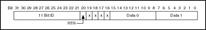
Mask/Comparator for Single-Standard Filter Mode |
|
The 11 Bit ID compares all 11 bits of standard IDs. The RTR bit determines whether the filter compares remote (0) or data (1) frames. Bits marked as "X" are reserved, and should be cleared to zero by the application. Data 0 compares the first data byte in the frame, and Data 1 compares the second data byte.
1 (Single Extended)
Filter all extended (29-bit) frames using a single mask/comparator filter.
The following figure describes the format of the Series 2 Mask and Series 2 Comparator attributes for this filter mode. |
|
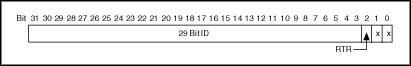
Mask/Comparator for Single-Extended Filter Mode |
|
The 29 Bit ID compares all 29 bits of extended IDs. The RTR bit determines whether the filter compares remote (0) or data (1) frames. Bits marked as "X" are reserved, and should be cleared to zero by the application.
2 (Dual Standard)
Filter all standard (11-bit) frames using a two separate mask/comparator filters. If either filter matches the frame, it is received. The frame is discarded only when neither filter detects a match.
The following figure describes the format of the Series 2 Mask and Series 2 Comparator attributes for this filter mode. |
|
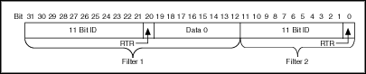
Mask/Comparator for Dual-Standard Filter Mode |
|
Filter 1 includes the 11 Bit ID, the RTR bit, and the first data byte in the frame. Filter 2 includes the 11 bit ID, and the RTR bit (no data).
3 (Dual Extended)
Filter all extended (29-bit) frames using a two separate mask/comparator filters. If either filter matches the frame, it is received. The frame is discarded only when neither filter detects a match.
The following figure describes the format of the Series 2 Mask and Series 2 Comparator attributes for this filter mode. |
|
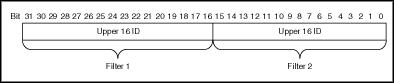
Mask/Comparator for Dual-Extended Filter Mode |
|
Each Upper 16 ID filter compares the 16 most significant bits of the 29-bit extended ID.
Single Shot Transmit?
Specifies whether to retry failed CAN frame transmissions (Series 2, 847x CAN, and 847x with Sync CAN interfaces only).
Communication must be stopped to set this attribute. Use Start On Open False with ncConfigCANNet.vi, set the attribute, then use ncAction to start communication.
0 | Zero Enables retry as defined in the CAN specification (default). If a CAN frame is not transmitted successfully, the CAN controller will immediately retry. |
1 | One
Single shot transmit. If a CAN frame is not transmitted successfully, the CAN controller will not retry. |
For Series 1, 847x LIN, and 847x with Sync LIN interfaces, this attribute must be left at its default (zero).
This attribute is available only for the Network Interface,
not CAN Objects.
Termination
Specifies the termination setting for your hardware. This attribute is not supported on Series 1, Series 2, USB-8473, or USB-8473s hardware. The values for this attribute are:
LS CAN
| 0 |
1.11 kΩ (Default) |
When set to 0 on USB-8472 or USB-8472s hardware, the termination is set to 1.11 kΩ. |
| 1 |
4.99 kΩ |
When set to 1 on USB-8472 or USB-8472s hardware, the termination is set to 4.99 kΩ. |
LIN
| 0 |
Disabled (Default) |
When set to 0 on USB-8476 or USB-8476s hardware, the termination is disabled. |
| 1 |
Enabled |
When set to 1 on USB-8476 or USB-8476s hardware, the termination is enabled. |
Timeline Recovery
Specifies whether to configure the CAN Network Interface Object to recover the original timeline when a timestamped transmit is late.
This attribute is applicable only when the Transmit Mode attribute is set to Timestamped Transmit (1).
Due to factors such as CAN bus arbitration, the time that a frame transmits successfully may be later than the original time specified. When a timestamped transmit is late, this attribute determines how NI-CAN will adjust transmit times for subsequent frames.
The values for this attribute are:
0 (FALSE)
Do not recover the original timeline.
Frames always transmit with the original gap or greater. This behavior is useful when you need to maintain a minimum gap between frames. The following figure shows an original timeline of three frames with a 10 ms gap. When frame B transmits 3 ms late, frame C continues to transmit 10 ms later, so the actual timeline slips.
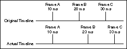
Example with Time Recovery Disabled
1 (TRUE)
Recover the original timeline.
When a timestamped transmit is late, the subsequent frame will transmit with a reduced gap. This behavior is useful when you need to maintain a timeline, such as when synchronizing CAN output with analog or digital output. The following figure shows an original timeline of three frames with a 10 ms gap. When frame B transmits 3 ms late, frame C transmits 7 ms later in order to recover the timeline.
The default value for this attribute is FALSE.
This attribute has to be set prior to starting the CAN Network Interface Object.
This attribute applies only to Series 1 and Series 2 hardware.
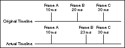
Example with Time Recovery Enabled
Timestamp Format
Sets the format of the timestamps reported by the on-board timer on the CAN or LIN hardware.
The default value for this attribute is Absolute.
The values for this attribute are:
0 (Absolute)
Sets the timestamp format to absolute. In the absolute format, the timestamp returned by NI-CAN read functions is the LabVIEW date/time format (DBL representing the number of seconds elapsed since 12:00 a.m., Friday, January 1, 1904).
1 (Relative)
Sets the timestamp format to relative. In the relative format, the timestamp returned by the NI-CAN read functions will be zero based (DBL representing the number of seconds since the start trigger occurred).
A typical use case for this attribute would be if data received from two RTSI synchronized CAN or LIN cards is to be correlated. For that use case, this attribute must be set to 1 for all of the CAN or LIN cards being synchronized. Setting this attribute on one port of a 2-port card will also reset the timestamp of the second port, since resetting the timestamp on the port resets the on-board timer.
This attribute should be set prior to starting any communication on the CAN or LIN hardware.
Transceiver External Outputs
Sets the transceiver external outputs for the Network Interface.
This attribute is available only for the Network Interface, not CAN Objects. Nevertheless, the attribute applies to communication by CAN Objects as well as the associated Network Interface.
Series 2 XS cards enable connection of an external transceiver. For an external transceiver, this attribute allows you to set the output voltage on the MODE0 and MODE1 pins of the CAN port, and it allows you control the sleep mode of the on-board CAN controller chip.
For many models of CAN transceiver, EN and NSTB pins control the transceiver mode, such as whether the transceiver is sleeping, or communicating normally. For such transceivers, you can wire the EN and NSTB pins to the MODE0 and MODE1 pins of the CAN port.
The default value of this attribute is 00000003 hex. For many models of transceiver, this specifies normal communication mode for the transceiver and CAN controller chip. If the transceiver requires a different MODE0/MODE1 combination for normal mode, you can use external inverters to change the default 5 V to 0 V.
This attribute is supported for Series 2 XS cards only. This attribute is not supported when the Transceiver Type is any value other than External. To control the mode of an internal transceiver, use the Transceiver Mode attribute.
This attribute uses a bit mask. Use bitwise OR operations to set multiple values.
00000001 hex (MODE0)
Set this bit to drive 5 V on the MODE0 pin. This is the default value. This bit is set automatically when a remote wakeup is detected.
Clear this bit to drive 0 V on the MODE0 pin.
00000002 hex (MODE1)
Set this bit to drive 5 V on the MODE1 pin. This is the default value. This bit is set automatically when a remote wakeup is detected.
Clear this bit to drive 0 V on the MODE1 pin.
00000100 hex (Sleep CAN controller chip)
Set this bit to place the CAN controller chip into sleep mode. This bit controls the mode of the CAN controller chip (sleep or normal), and the independent MODE0/MODE1 bits control the mode of the external transceiver. When you set this bit to place the CAN controller into sleep mode, you typically specify MODE0/MODE1 bits that place the external transceiver into sleep mode as well.
When the CAN controller is asleep, a remote wakeup will automatically place the CAN controller into its normal mode of communication. In addition, the MODE0/MODE1 pins are restored to their default values of 5 V. Therefore, a remote wakeup causes this attribute to change from the value that you set for sleep mode, back to its default 00000003 hex. You can determine when this has occurred by getting Transceiver External Outputs using ncGetAttr.vi. For more information on remote wakeup, refer to the Transceiver Mode attribute for internal transceivers.
Clear this bit to place the CAN controller chip into normal communication mode. If the CAN controller was previously in sleep mode, this performs a local wakeup to restore communication.
Transceiver Mode
Sets the transceiver mode for the Network Interface. The transceiver mode controls whether the transceiver is asleep or communicating, as well as other special modes.
This attribute is available only for the Network Interface, not CAN Objects. Nevertheless, the attribute applies to communication by CAN Objects as well as the associated Network Interface.
This attribute is supported on Series 2, 847x CAN, and 847x with Sync CAN interfaces only.
For Series 2 cards for the PCMCIA form factor, this property requires a corresponding Series 2 cable (dongle). For information on how to identify the series of the PCMCIA cable, refer to Series 2 Vs. Series 1.
For Series 2 XS cards, this attribute is not supported when the Transceiver Type is External. To control the mode of an external transceiver, use the Transceiver External Outputs attribute.
The default value for this attribute is Normal.
This attribute uses the following values:
0 (Normal)
Set transceiver to normal communication mode. If you set Sleep mode previously, this performs a local wakeup of the transceiver and CAN controller chip.
1 (Sleep)
Set transceiver and the CAN controller chip to sleep (or standby) mode.
If the transceiver supports multiple sleep/standby modes, the NI CAN hardware implementation ensures that all of those modes are equivalent with regard to the transceiver's behavior on the network. For more information on the physical specifications of each transceiver's normal and sleep modes, refer to NI CAN and LIN Hardware.
You can set Sleep mode only while the interface is communicating. If the Network Interface has not been started, setting the transceiver mode to Sleep will return an error.
When the interface enters sleep mode, communication is not possible until a wakeup occurs. All pending frame transmissions are deferred until the wakeup occurs. The transceiver and CAN controller wake from sleep mode when either a local wakeup or remote wakeup occurs.
A local wakeup occurs when the application sets the transceiver mode to Normal (or some other communication mode).
A remote wakeup occurs when a remote node transmits a CAN frame (referred to as the wakeup frame). The wakeup frame wakes up the transceiver and CAN controller chip of the NI CAN interface. The wakeup frame is not received or acknowledged by the CAN controller chip. When the wakeup frame ends, the NI CAN interface enters Normal mode, and again receives and transmits CAN frames. If the node that transmitted the wakeup frame did not detect an acknowledgement (such as if other nodes were also waking), it will retry the transmission, and the retry will be received by the NI CAN interface.
For a remote wakeup to occur for Single Wire transceivers, the node that transmits the wakeup frame must first place the network into the Single Wire Wakeup Transmission mode by asserting a higher voltage (typically 12 V). For more information, refer to mode 2.
When the local or remote wakeup occurs, frame transmissions resume from the point at which the original Sleep was set.
You can detect when a remote wakeup occurs by using ncGetAttr.vi with the Transceiver Mode attribute. If you need to suspend the application while waiting for the remote wakeup, use the Remote Wakeup state of ncWaitForState.vi.
2 (Single Wire Wakeup)
Set Single Wire transceiver to Wakeup Transmission mode.
This mode is supported on Single Wire (SW) ports only.
The Single Wire Wakeup Transmission mode drives a higher voltage level on the network to wakeup all sleeping nodes. Other than this higher voltage, this mode is similar to Normal mode. CAN frames can be received and transmitted normally.
Since you use the Single Wire Wakeup mode to wakeup other nodes on the network, it is not typically used in combination with Sleep mode for a given interface.
The timing of how long the wakeup voltage is driven is controlled entirely by the application. The application will typically change to Single Wire Wakeup mode, transmit a wakeup frame, then return to Normal mode.
The following sequence demonstrates a typical sequence of steps for sleep and wakeup between two Single Wire NI CAN interfaces. The sequence assumes that CAN0 is the sleeping node, and CAN1 originates the wakeup.
Start both CAN0 and CAN1. Both use the default Normal mode. Set Transceiver Mode of CAN0 to Sleep. Set Transceiver Mode of CAN1 to Single Wire Wakeup. Write data to CAN1 to transmit a wakeup frame to CAN0. Set Transceiver Mode of CAN1 to Normal. Now both CAN0 and CAN1 are in Normal mode again.
3 (Single Wire High-Speed)
Set Single Wire transceiver to High-Speed Transmission mode.
This mode is supported on Single Wire (SW) ports only.
The Single Wire High-Speed Transmission mode disables the internal waveshaping function of the transceiver, which allows baud rates up to 100 kbytes/s to be used. The disadvantage versus Normal (which allows up to 40 kbytes/s baud) is degraded EMC performance. Other than the disabled waveshaping, this mode is similar to Normal mode. CAN frames can be received and transmitted normally.
This mode has no relationship to High-Speed (HS) transceivers. It is merely a higher speed mode of the Single Wire (SW) transceiver, typically used for downloading large amounts of data to a node.
The Single Wire transceiver does not support use of this mode in conjunction with Sleep mode. For example, a remote wakeup cannot transition from Sleep to this Single Wire High-Speed mode.
Transceiver Type
For XS Software Selectable Physical Layer cards that provide a software-switchable transceiver, the Transceiver Type attribute sets the type of transceiver. When the transceiver is switched from one type to another, NI-CAN ensures that the switch is undetectable from the perspective of other nodes on the network.
The default value for this attribute is specified within MAX. If you change the transceiver type in MAX to correspond to the network in use, you can avoid setting this attribute within the application.
This attribute is available only for the Network Interface, not CAN Objects. Nevertheless, the attribute applies to communication by CAN Objects as well as the associated Network Interface.
Communication for all objects on the Network Interface must be stopped prior to setting this attribute. You typically do this by calling ncConfigNet.vi with Start On Open set to false, then ncOpen.vi of the Network Interface, then ncSetAttr.vi to set Transceiver Type, then ncAction.vi to start communication. Prior to changing the Transceiver Type again, you must use ncAction.vi to stop communication.
You can only set this attribute for Series 2 XS interfaces.
This attribute uses the following values:
0 (High-Speed)
Switch the transceiver to High-Speed (HS).
1 (Low-Speed/Fault-Tolerant)
Switch the transceiver to Low-Speed/Fault-Tolerant (LS).
2 (Single Wire)
Switch the transceiver to Single Wire (SW).
3 (External)
Switch the transceiver to External. The External type allows you to connect a transceiver externally to the interface. For more information on connecting transceivers externally, refer to NI CAN and LIN Hardware.
When this transceiver type is selected, you can use the Transceiver External Outputs and Transceiver External Inputs attributes to access the external mode and status pins of the connector.
4 (Disconnect)
Disconnect the CAN controller chip from the connector. This value is used when you physically switch an external transceiver. You first set Transceiver Type to Disconnect, then switch from one external transceiver to another, then set Transceiver Type to External. For more information on connecting transceivers externally, refer to NI CAN and LIN Hardware.
Transmit Mode
Specifies whether to configure the CAN Network Interface Object to Immediate Transmit mode or Timestamped Transmit mode.
The default value for this attribute is zero (Immediate Transmit).
The values for this attribute are:
0 (Immediate Transmit)
Configures the Network Interface Object in the Immediate Transmit mode. In the Immediate Transmit mode, the CAN frames are transmitted as soon as they are written into the Network Interface Object's write queue. CAN frames can be written into the Network Interface Objects write queue by either using ncWriteNet.vi or ncWriteNetMult.vi. Timestamps are ignored by NI-CAN when the Network Interface Object is configured in this mode.
1 (Timestamped Transmit)
Configures the Network Interface Object in the Timestamped Transmit mode. In this mode, NI-CAN spaces the frame transmission according to the difference in timestamps between consecutive frames. For example, if every frame provided to ncWriteNetMult.vi increments by 10 milliseconds, the frames will be transmitted with a 10 millisecond gap.
If the timestamp of the CAN frame to be transmitted is less than the timestamp of the previous CAN frame, Timestamped Transmit is reset and the CAN frame will be transmitted immediately on the bus without adding any delay. For example, if you write a frame with a relative timestamp 30 ms followed by a frame with a timestamp 15 ms, the two frames will be transmitted back to back.
Use ncWriteNetMult.vi to write CAN frames with timestamps into the write queue of the Network Interface Object.
To use the ncWriteNet.vi in Timestamped Transmit mode, refer to the description of ncWriteNet.vi.
This attribute has to be set prior to starting the CAN Network Interface Object.
This attribute applies only to Series 1 and Series 2 interfaces.
User RTSI Frame
Sets the user RTSI frame. This attribute is normally configured using the UserRTSIFrame input of ncConfigCANObjRTSI. This attribute allows that value to be changed while running. For more information, refer to ncConfigCANObjRTSI.
This attribute is available only for CAN Objects, not the Network Interface.
Virtual Bus Timing
Sets the Virtual Bus Timing of the virtual device.
The values for this attribute are:
0 (FALSE)
Virtual Bus Timing is turned off. By turning Virtual Bus Timing off, the CAN bus simulation is disabled and CAN frames are copied from the write queue of one virtual interface to the read queue of the second virtual interface. This setting is useful if you desire to only convert frames to channels or vice versa and not simulate actual CAN bus communication.
1 (TRUE)
Virtual Bus Timing is turned on (default). By turning Virtual Bus Timing on, frame timestamps are recalculated as they transfer across the virtual bus. This mode is useful when you want the virtual bus to behave as much like a real bus as possible.
If this attribute is set on real hardware, an error will be returned.
The Virtual Bus Timing has to be set to the same value on both virtual interfaces.
This attribute must be set prior to starting the virtual interface.
Refer to Frame to Channel Conversion for more information.
|
|