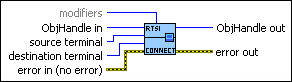
ncConnectTerminals.vi
Purpose
Connect a terminal in the CAN or LIN hardware.
Format
Inputs
 | ObjHandle in is the object handle from the previous NI-CAN VI. The handle reference originated from ncOpen.vi. | ||||||
 | source terminal specifies the source of the connection. Once the connection is successfully created, behavior flows from source terminal to destination terminal. For a list of valid source/destination pairs, refer to Valid Combinations of Source/Destination. The following list describes each value of source terminal: RTSI0 ... RTSI6 Selects a general-purpose RTSI line as source (input) of the connection. RTSI7/RTSI Clock Selects RTSI line 7 as source (input) of the connection. RTSI7 is dedicated for routing of a timebase. RTSI7 is also known as RTSI Clock in some National Instruments software products, such as NI-DAQ. For PCI and PXI form factors, this receives a 20 MHz (default) timebase from another CAN or DAQ card. For example, you can synchronize a CAN and DAQ E Series MIO card by connecting the 20 MHz oscillator (board clock) of the DAQ card to RTSI7/RTSI Clock, and then connecting RTSI7/RTSI Clock to Master Timebase on the CAN card. For PCMCIA form factor, a 10 MHz timebase is required on RTSI7/RTSI Clock. For synchronization with a PCMCIA DAQ card, this is done by programming FREQOUT signal of the DAQ card to 10 MHz, then wiring FREQOUT to the RTSI7/RTSI Clock of the CAN card. For the 847x with Sync series CAN and LIN interfaces, 1 MHz, 10 MHz, and 20 MHz are valid timebases. Refer to USB-CAN and USB-LIN Specifications for details on synchronization triggers. This value does not apply to Series 1. PXI_Star PXI_Star selects the PXI star trigger signal. Within a PXI chassis, some PXI products can source a star trigger from Slot 2 to all higher-numbered slots. PXI_Star enables the PXI CAN card to receive the star trigger when it is in Slot 3 or higher. This value applies to Series 2 PXI CAN cards only. PXI_Clk10 PXI_Clk10 selects the PXI 10 MHz backplane clock. This routes the 10 MHz PXI backplane clock for use as the timebase of the CAN card. When you use PXI_Clk10 as the timebase for the CAN card, you must also use PXI_Clk10 as the timebase for other PXI cards to perform synchronized input/output. This value applies to Series 2 PXI CAN cards only. 20 MHz Timebase 20 MHz Timebase selects the local oscillator of the CAN or LIN hardware. The only valid destination terminal for this source is RTSI7/RTSI Clock. This routes the local clock of the hardware for use as a timebase by other NI cards. For example, you can synchronize two CAN cards by connecting 20 MHz Timebase to RTSI7/RTSI Clock on one CAN card and then connecting RTSI7/RTSI Clock to Master Timebase on the other CAN card. 20 MHz Timebase applies to the entire CAN or LIN hardware, including both interfaces of a 2-port CAN card. This value applies to Series 2 PXI or PCI CAN cards and 847x with Sync interfaces only. For 847x with Sync series CAN and LIN interfaces the internal oscillator runs at 1 MHz. 10 Hz Resync Clock 10 Hz Resync Clock selects a 10 Hz, 50 percent duty cycle clock. This slow rate is required for resynchronization of Series 1 CAN cards. On each pulse of the resync clock, the other CAN card brings its clock into sync. By selecting RTSI0 to RTSI6 as the destination terminal, you route the 10 Hz clock to synchronize with other Series 1 CAN cards. NI-DAQ or NI-DAQmx cards cannot use the 10 Hz resync clock, so this selection is limited to synchronization of two or more CAN cards. 10 Hz Resync Clock applies to the entire CAN card, including both interfaces of a 2-port CAN card. This value applies to Series 1 and Series 2 CAN cards, but is typically used with Series 1 CAN cards only. If all of the CAN cards are Series 2, the 20 MHz timebase is preferable due to the lack of drift. Interface Receive Event Interface Receive Event selects the dedicated receive interrupt output on the Philips SJA1000 CAN controller. When a received frame successfully passes the acceptance filter, a pulse with the width of one bit time is output during the last bit of the end of frame position of the CAN frame. Incoming CAN frames can be filtered using the Series 2 Filter Mode attribute. The CAN controller is specified by the ObjName input to ncOpen.vi. The Interface Receive Event can be used as the start trigger for other NI cards, or for external instruments. This value applies to Series 2 cards only. Interface Transceiver Event Interface Transceiver Event selects the NERR signal from the CAN transceiver. The Low-Speed/Fault-Tolerant transceiver and the High-Speed transceiver provide the NERR signal. This signal asserts when the transceiver detects a fault. The default value of NERR is logic-high, which indicates no error. The CAN controller is specified by the ObjName input to ncOpen.vi. This value applies to Series 2 CAN cards only. Start Trigger Start Trigger selects the start trigger, the event that starts objects. The start trigger is the same for all tasks using a given interface, as specified by the ObjName input to ncOpen.vi. In the default (disconnected) state of the Start Trigger destination, the start trigger occurs when communication begins on the interface. By selecting RTSI0 to RTSI6 as the destination terminal, you route the start trigger of this CAN or LIN hardware to the start trigger of other CAN, LIN, or DAQ hardware. This ensures that sampling begins at the same time on both cards. For example, you can synchronize two CAN cards by routing Start Trigger as the source terminal on one CAN card and then routing Start Trigger as the destination terminal on the other CAN card, with both cards using the same RTSI line for the connections. | ||||||
|
destination terminal specifies the destination of the connection. The following list describes each value of destination terminal: RTSI0 ... RTSI6 Selects a general-purpose RTSI line as destination (output) of the connection. RTSI7/RTSI Clock Selects RTSI line 7 as destination (output) of the connection. RTSI7 is dedicated for routing of a timebase. RTSI7 is also known as RTSI Clock in some National Instruments software products, such as NI-DAQ or NI-DAQmx. Series 2 CAN cards can import a 10 MHz or 20 MHz timebase, but can export only a 20 MHz timebase. 847x with Sync cards can import 1 MHz, 10 MHz, or 20 MHz timebases, but can export only a 1 MHz timebase. Master Timebase Master Timebase instructs the CAN or LIN hardware to use the source of the connection as the master timebase. The CAN or LIN hardware uses this master timebase for input sampling (including timestamps of received messages) as well as periodic output sampling. For PCI and PXI form factors, you can use RTSI7/RTSI Clock as the source terminal. By default this receives a 20 MHz timebase from another CAN or DAQ card. For example, you can synchronize a CAN and DAQ E Series MIO card by connecting the 20 MHz oscillator (board clock) of the DAQ card to RTSI7/RTSI Clock, and then connecting RTSI7/RTSI Clock to Master Timebase on the CAN card. To change the Master Timebase Rate to 10 MHz, use ncSetAttr.vi to change the Master Timebase Rate attribute. For PXI form factor, you also can use PXI_Clk10 as the source terminal. This receives the PXI 10 MHz backplane clock for use as the master timebase. For PCMCIA form factor, you can use RTSI7/RTSI Clock as the source terminal. Unlike PCI and PXI, the PCMCIA CAN card requires a 10 MHz timebase on RTSI7/RTSI Clock. For synchronization with a PCMCIA DAQ card, this is done by programming the FREQOUT signal of the DAQ card to 10 MHz, then wiring FREQOUT to the RTSI7/RTSI Clock of the CAN card. For the USB form factor, you can use RTSI7/RTSI Clock as the source terminal. The USB hardware automatically senses the incoming clock rate of 1 MHz, 10 MHz, or 20 MHz, so no further configuration is required. Master Timebase applies to the entire CAN or LIN hardware, including both interfaces of a 2-port CAN card. The default (disconnected) state of this destination means the CAN or LIN hardware uses its local timebase as the master timebase. 10 Hz Resync Clock 10 Hz Resync Clock instructs the CAN card to use a 10 Hz, 50 percent duty cycle clock to resynchronize its local timebase. This slow rate is required for resynchronization of CAN cards. On each low-to-high transition of the resync clock, this CAN card brings its local timebase into sync. When synchronizing to an E Series MIO card, a typical use of this value is to use RTSI0 to RTSI6 as the source terminal, then use NI-DAQ or NI-DAQmx functions to program the Counter 0 of the MIO card to generate a 10 Hz 50 percent duty cycle clock on the RTSI line. When synchronizing to a CAN card, a typical use of this value is to use RTSI0 to RTSI6 as the source terminal, then route the 10 Hz Resync Clock of the other CAN card as the source terminal to the same RTSI line. 10 Hz Resync Clock applies to the entire CAN card, including both interfaces of a 2-port CAN card. The CAN card is specified by the ObjName input to ncOpen.vi. The default (disconnected) state of this destination means the CAN card does not resynchronize its local timebase. This value applies to Series 1 and Series 2 CAN cards, but is typically used with Series 1 CAN cards only. If all of the CAN cards are Series 2, the 20 MHz timebase is preferable due to the lack of drift. If you are using a mix of Series 1 and Series 2 CAN cards, you must use the 10 Hz Resync Clock. Start Trigger Start Trigger selects the start trigger, the event that starts communication for all CAN objects on the same port. The start trigger occurs on the first low-to-high transition of the source terminal. The start trigger is the same for all CAN Objects using a given interface, as specified by the ObjName input to ncOpen.vi. By selecting RTSI0 to RTSI6, or PXI_Star for PXI hardware, as the source terminal, you route the start trigger from another CAN, LIN, or DAQ card. This ensures that sampling begins at the same time on both cards. For example, you can synchronize with an E Series DAQ MIO card by routing the AI start trigger of the MIO card to a RTSI line and then routing the same RTSI line with Start Trigger as the destination terminal on the CAN card. The default (disconnected) state of this destination means the start trigger occurs when communication begins on the interface. | ||||||
| modifiers provides optional connection information for certain source/destination pairs. The current release of NI-CAN does not use this information for any source/destination pair, so modifiers must be left unwired. | ||||||
 |
Error in describes error conditions occurring before the VI executes. If an error has already occurred, the VI returns the value of the Error in cluster in Error out.
|


Outputs
| ObjHandle out is the object handle for the next VI. | ||||||
|
Error out describes error conditions. If the Error in cluster indicated an error, the Error out cluster contains the same information. Otherwise, Error out describes the error status of this VI.
|
Description
This VI connects a specific pair of source/destination terminals. One of the terminals is typically a RTSI signal, and the other terminal is an internal terminal in the CAN or LIN hardware. By connecting internal terminals to RTSI, you can synchronize the CAN or LIN hardware with another hardware product such as an NI-DAQ or NI-DAQmx card.
When the final CAN object for a given port is cleared with ncClose.vi, NI-CAN disconnects all terminal connections for that port. Therefore, ncDisconnectTerminals.vi is not required for most applications. NI-DAQ and NI-DAQmx terminals remain connected after the CAN objects are cleared, so you must disconnect NI-DAQ and NI-DAQmx terminals manually at the end of the application.
For a list of valid source/destination pairs, refer to the following section.
Valid Combinations of Source/Destination
The series of the NI CAN hardware determines what combinations of source terminal to destination terminal are valid. Within the table, 1 indicates Series 1 hardware, 2 indicates Series 2 hardware, and 3 indicates 847x with Sync series hardware. You can determine the series of the NI CAN hardware by selecting the name of the card within the Devices and Interfaces view in the left pane of MAX.
Series 1 hardware has the following limitations.
- PXI cards do not support RTSI6.
- Signals received from a RTSI source cannot occur faster than 1 kHz. This prevents the card from receiving a 10 MHz or 20 MHz timebase, such as NI E Series MIO hardware provides.
- Signals received from a RTSI source must be at least 100 µs in length to be detected. This prevents the card from receiving triggers in the nanoseconds range, such as the AI trigger that E Series MIO hardware provides. Series 2 CAN cards also send RTSI pulses in the nanoseconds range, so Series 1 CAN cards cannot receive RTSI input from Series 2 CAN cards.
- For CAN cards with High-Speed (HS) ports only, four RTSI signals are available for input (source), and four RTSI signals are available for output (destination). This limitation applies to the number of signals per direction, not the RTSI signal number. For example, if you connect RTSI0, RTSI1, RTSI3, and RTSI5 as input, connecting RTSI4 as input will return an error.
- For CAN cards with one or more Low-Speed (LS) ports, two RTSI signals are available for input (source), and three RTSI signals are available for output (destination).
Series 2 hardware has the following limitations.
- For all form factors (PCI, PXI, PCMCIA), the connection of Interface Transceiver Event to a RTSI destination depends on the physical port location. If the interface is on Port 1, you can connect to only even-numbered RTSI lines (RTSI0, RTSI2, RTSI4, RTSI6). If the interface is on Port 2, you can connect to only odd-numbered RTSI lines (RTSI1, RTSI3, RTSI5). You can determine the location by selecting the name of the interface in MAX.
- PCI cards do not support the PXI_Star and PXI_Clk10 terminals, as those signals exist on the PXI backplane.
- PCMCIA cards do not support the 20 MHz Timebase, PXI_Star, and PXI_Clk10 terminals. Because 20 MHz Timebase is not supported, you cannot synchronize the timebases of two PCMCIA CAN cards.
- On PCMCIA cards, RTSI4 , RTSI5 and RTSI6 are not available.
847x with Sync series hardware has the following limitations.
- No support for RTSI1–RTSI6.
- Because 20 MHz timebase only outputs a 1 MHz signal, you cannot source a timebase to a PCI-CAN device++. It can, however, receive a 20 MHz signal from a PCI-CAN device.
- RTSI0 must be connected to the TRIG terminal and RTSI7 must be connected to the CLK terminal. Refer to USB-LIN for more information on the pinout of the USB-847x with Sync series hardware.
The following table lists all valid combinations of source terminal and destination terminal.
| Source | Destination | ||||
|---|---|---|---|---|---|
| RTSI0 to RTSI6 | RTSI_CLOCK | Master Timebase | 10 Hz Resync Clock | Start Trigger | |
| RTSI0 to RTSI6 | — | — | — | 1,2 | 1,2,3 |
| RTSI7/RTSI Clock | — | — | 2,3 | — | — |
| PXI_Star | — | — | — | — | 2 |
| PXI_Clk10 | — | — | 2 | — | — |
| 20 MHz Timebase | — | 2,3 | — | — | — |
| 10 Hz Resync Clock | 1,2 | — | — | — | 1,2 |
| Interface Receive Event | 2 | — | — | — | 2 |
| Interface Transceiver Event | 2 | — | — | — | — |
| Start Trigger Event | 1,2,3 | — | — | — | — |
1—Valid connection for Series 1 hardware
2—Valid connection for Series 2 hardware
2—Valid connection for 847x with Sync series hardware