Frame to Channel Conversion
As described in the NI-CAN Software Overview, NI-CAN supports two distinct formats for CAN data. The first format is the CAN frame, which represents a raw frame consisting of an ID, type, data bytes, and timestamp. The second format is the CAN channel, which represents a field in the data of a specific ID, scaled to a floating point value in physical units (such as Volts or Revolutions-per-minute).
Many applications require the ability to convert CAN data from one format to another. As one example, consider an application that logs CAN traffic to a file for an extended period of time. Since CAN frames occur in an event driven manner, the most efficient means of file storage is to use CAN frames as the data format. Nevertheless, when displaying the contents of the log file, you may need to plot the data as waveforms for specific CAN channels. Therefore, the application must convert the CAN frames in the file into CAN channels for waveform display.
The following figure demonstrates how you can use NI-CAN to display waveforms of CAN channels using a log file consisting of CAN frames. NI-CAN provides a virtual CAN card with two interfaces, CAN256 and CAN257. The two virtual interfaces are connected by a virtual bus. When you write CAN frames to one virtual interface, those frames are received by the other virtual interface, and can be read as channels. This feature allows you to read and write CAN data in the same manner as two real CAN interfaces connected by a real CAN cable. The conversion does not require real NI CAN hardware, and your application is not required to check for specific CAN IDs.
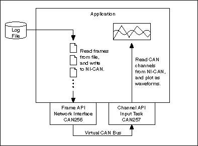
Display waveforms of CAN channels using a log file of CAN frames
When Should I Use Frame to Channel Conversion?
The following sections outline some applications that use frame to channel conversion, channel to frame conversion, or other aspects of the virtual interface concept.
Logging
As explained in the Introduction, logging is one of the primary applications for frame to channel conversion. Since overall CAN traffic does not occur at a fixed rate, the most efficient implementation is to store each CAN frame as it is received. The file of CAN frames can later be displayed as channels using NI-CAN's frame to channel conversion.
In addition to displaying a log file as channels, you can also use NI-CAN to create a log file using channel data. The process for this channel to frame conversion is essentially a reversal of the operations shown in the figure above. You obtain CAN channel data from front panel controls, and write that CAN channel data to a Channel API output task on a virtual interface (CAN257). Next, you read the resulting CAN frames from a Frame API virtual interface (CAN256), and write those frames to the log file. At a subsequent date, you can replay this log file to a real CAN interface using the timestamped transmit feature (Transmit Mode attribute of the Frame API network interface).
Although NI-CAN examples demonstrate a simple binary log file format, your logging or replay application can access any file format that you require. Although there is a wide variety of CAN log file formats available from other companies, almost all use CAN frames as the fundamental data type. Once you obtain the specification for a specific CAN log file format, it is relatively straightforward to convert the file contents to data that is compatible with the NI-CAN Frame API.
CompactRIO
The rugged enclosure and real-time capabilities of CompactRIO, as discussed in CAN for CompactRIO, make it an ideal product for testing in the field, such as drive testing of an automobile. Since the LabVIEW FPGA I/O interface for CAN provides access to CAN frames only, you must use NI-CAN's frame to channel conversion features when access to CAN channels is required.
For logging applications, the LabVIEW application on CompactRIO is simple: read CAN frames and store them in a file. When the CAN log file is later transferred from CompactRIO to a lab computer, the application on that computer can use NI-CAN to read frames from the log file and display as CAN channels, as shown in Figure 1. In addition, if the LabVIEW application on CompactRIO stores a second log file with analog/digital samples, that data can be displayed on the lab computer as waveforms synchronized with the CAN channels.
For applications in which you must execute a control model within CompactRIO, you typically wire CAN channels as inputs and outputs to the control model. In order to implement this, you can install NI-CAN on the LabVIEW RT controller of CompactRIO. Your LabVIEW FPGA VI reads and writes CAN frames, and transfers those CAN frames to/from LabVIEW RT as you would any other I/O. Your LabVIEW RT VI uses NI-CAN's virtual interfaces to convert the CAN frames to/from CAN channels. Your NI-CAN Channel API tasks use sample rate 0 and single-sample read/write, thus providing immediate single-point values for the control model.
Development without CAN Hardware
The virtual interface can enable development of an NI-CAN application on a computer that does not contain NI CAN hardware. Although the NI-CAN virtual interface does impose some Limitations, most functions return successful status. In addition, the virtual bus feature may enable you to debug your application by simulating limited CAN traffic. For example, if your application is intended to test a CAN node, you can run your test on CAN256, and run a simple simulation of the node on CAN257.
Database Queries
For large test applications that are deployed to several end-users, it is common to query CAN databases for initial configuration of a test. For example, you specify a list of channel names, each with parameters for display in a single waveform graph, then save that test configuration to a file. The application that queries the CAN database to create a test configuration file often executes on a system without NI CAN hardware.
By initializing a Channel API task on CAN256, you can use the CAN Get Property function to obtain detailed information for each message and channel in a CAN database.
Enhance an Existing Frame API Application
You have a large Frame API application for an older version of NI-CAN (1.x), and that application can benefit from display of CAN data as channels. Rather than changing all of the application's CAN communication from the Frame API to the Channel API, you can use frame to channel conversion to enhance the existing code. For example, the bulk of the application can communicate on a real interface (i.e. CAN0) using the Frame API, but you can add code that uses virtual interfaces to convert raw frame data to/from channel data for additional displays.
USB-847x
The USB-847x hardware is supported only by the Frame API. For some applications with the USB-847x you may want to display CAN data as channels. In this case you can use frame to channel conversion to convert the frame data into channel data for display.
Virtual Bus Timing
The NI-CAN virtual interface provides an attribute that does not exist on real interfaces. Virtual Bus Timing is a boolean attribute that specifies whether the time between successive CAN frames is simulated by NI-CAN when the frames transfer across the virtual bus.
When Virtual Bus Timing is true (default), the time between frames is simulated. Frame timestamps are recalculated as they transfer across the virtual bus. This mode is useful when you want the virtual bus to behave as much like a real bus as possible. For example, if you use the technique shown in Figure 1 to display a log file that was captured over 200 seconds of time, the channel waveforms will scroll slowly to display data for 200 seconds. This is due to the fact that when you write two frames whose timestamps are a few seconds apart, NI-CAN will delay a few seconds on the virtual bus, and therefore the Channel API Read of CAN257 will delay between the two frames. The programming model used to write NI-CAN applications for real CAN hardware can be used for a majority of applications with Virtual Bus Timing enabled. Refer to the Channel API Basic Programming Model and the Frame API Basic Programming Model for information on programming real CAN hardware.
When Virtual Bus Timing is false, the time between frames is not simulated. Frame timestamps are unchanged as they transfer across the virtual bus. This mode is useful when you want to convert CAN data from frames to channels as quickly as possible. For example, if you use the technique shown in Figure 1 to display a log file that was captured over 200 seconds of time, the channel waveforms will scroll by very quickly. This is due to the fact that when you write two frames whose timestamps are a few seconds apart, NI-CAN will not delay the transfer on the virtual bus, and therefore the Channel API Read of CAN257 will not delay between the two frames. Although the conversion occurs quickly, you will presumably use products like LabVIEW or DIAdem to search the waveforms for specific events. When Virtual Bus Timing is disabled, time advances only up to the timestamp of the last frame written onto the virtual bus. As a result, if NI-CAN detects that a frame with a timestamp lesser than the previous frame timestamp is being written onto the virtual bus, an error will be returned. Refer to the Programming Model for Virtual Bus Timing Disabled for information on developing an application that converts frames to channels or channels to frames without simulating frame timing.
When you change the Virtual Bus Timing in your application, you must set the same value on both virtual interfaces, CAN256 and CAN257.
Limitations
The virtual interface is not designed to support all of the features of a real interface. This section serves as the primary reference for the limitations of the virtual interface.
For each NI-CAN feature, the virtual interface will behave in one of three ways:
- Error—The NI-CAN function returns an error. This occurs for features that are not supported, and which represent high-level capabilities that your application would require. For example, the virtual interface does not support Frame API CAN Objects, so the error helps to clarify that you cannot execute applications that rely on CAN Objects.
- Non-operational—The NI-CAN function returns success, but the feature performs in a fixed, non-operational manner. This occurs for features that your application typically would not rely on. For example, the virtual interface always returns zero for the Serial Number attribute, because your application may display the serial number, but operate correctly when the number is invalid.
- Operational—The NI-CAN function returns success, and operates as expected with regard to the virtual bus. For example, if you write a frame to a virtual network interface using the Frame API, that frame will transfer across the virtual bus to the other virtual interface.
The Error features for the virtual interface table lists all Error features for the virtual interface. The VBT column lists the values (T=true, F=false) of the Virtual Bus Timing attribute for which the Error behavior applies. If the VBT column lists both T and F, then Virtual Bus Timing does not affect the Error feature listed.
The Operational features for the virtual interface table lists all Operational features for the virtual interface. The VBT column lists the values (T=true, F=false) of the Virtual Bus Timing attribute for which the Operational behavior applies. If the VBT column lists both T and F, then Virtual Bus Timing does not affect the Operational features listed.
All features that are not explicitly listed in these tables are Non-operational. The behavior of Non-operational features is not documented in this manual. Your application should not make assumptions regarding the behavior of Non-operational features beyond the fact that NI-CAN returns success.
Error Features for the Virtual Interface
| Feature | VBT | Explanation |
|---|---|---|
| Channel API: Initialize of Output (or Output Recent) mode with Sample Rate greater than 0 | T, F | The virtual interface does not support periodic timing for transmit. For channel to frame conversion, you must set the Channel API sample rate to 0, and perform periodic timing within your application. |
| Channel API: Set Property of Timestamp Format | F | Since timestamps are not changed when Virtual Bus Timing is false, this attribute does not apply. |
| Frame API: Open of CAN Object | T, F | CAN Objects are not supported. For the Frame API, the virtual interface is limited to the Network Interface. |
| Frame API: Read (or ReadMult) of Delay frame | F | When virtual bus timing is disabled, the virtual interface does not simulate timing between frames, so the Delay frame does not apply. For information on the Delay frame, refer to ncWriteNetMult.vi (LabVIEW) or ncWriteMult (C/C++). |
| Frame API: Set Attribute of Log Comm Warnings | T, F | The special Comm Warnings frame is not supported on virtual interfaces. If you write this frame, it will not be received on the other interface. |
| Frame API: Set Attribute of Timestamp Format | F | Since timestamps are not changed when Virtual Bus Timing is false, this attribute does not apply. The error is returned when an interface or task is started. |
| Frame API: Set Attribute of Transmit Mode | F | Since timestamps are not interpreted when Virtual Bus Timing is false, this attribute does not apply. The error is returned when an interface or task is started. |
| Frame API: Wait (or CreateNotification or CreateOccurrence) for any state except Write Multiple | F | When virtual bus timing is disabled, the virtual interface is limited to quick conversion of frames to/from channels. The Write Multiple state remains useful for streaming of frames to channels, but other states do not apply. |
Operational Features for the Virtual Interface
| Feature | VBT | Explanation |
|---|---|---|
| Channel API: Clear | T, F | As with a real interface, the Channel API task for a virtual interface must be cleared. |
| Channel API: Get Property of Message or Channel properties | T, F | Useful for database queries. You pass the filepath for the database into the original Initialize function. |
| Channel API: Initialize of Input mode with Sample Rate equal 0 | T, F | Read most recent value for each channel. Useful for simulated control models. |
| Channel API: Initialize of Input mode with Sample Rate greater than 0 | T, F | Read periodically sampled values for each channel. Useful to display frames in waveform graphs. |
| Channel API: Initialize of Output (or Output Recent) mode with Sample Rate equal 0 | T, F | Write channel values to transmit a frame. Useful for simulated control models, or to create a log file. |
| Channel API: Initialize of Timestamped Input mode | T, F | Read timestamped samples. |
| Channel API: Read | T, F | Read channels that correspond to frames received from the virtual bus. All Read types are supported. |
| Channel API: Set Property of Timestamp Format | T | Determines whether to use absolute or relative timestamps when reading frames from the virtual bus. |
| Channel API: Start or Stop | T, F | Controls whether frames are transmitted to or received from the virtual bus. Start includes the InitStart function. |
| Channel API: Write | T, F | Write channels that correspond to frames transmitted to the virtual bus. All Write types are supported. |
| Frame API: Action of Start or Stop | T, F | Controls whether frames are transmitted to or received from the virtual bus. Action opcodes for Reset and RTSI Output are Non-operational. |
| Frame API: Close | T, F | As with a real Network Interface, the virtual Network Interface must be closed. |
| Frame API: Config of Network Interface | T, F | The only valid attribute is Start On Open. All other attributes are ignored. The only valid virtual interface names are CAN256 and CAN257. |
| Frame API: Get Attribute of Read Entries Pending | T, F | Returns the number of frames pending in virtual Network Interface read queue. |
| Frame API: Get Attribute of Read Mult Size for Notification | T | Returns the number of frames used as a threshold for the Read Multiple state. |
| Frame API: Get Attribute of Write Entries Free | T | Returns the number of frames that can be accepted to write without causing an overflow error. |
| Frame API: Get Attribute of Write Entries Pending | T, F | Returns the number of frames pending in virtual Network Interface write queue. |
| Frame API: Open of Network Interface | T, F | Config of the Network Interface is ignored (Non-operational). The only valid virtual interface names are CAN256 and CAN257. |
| Frame API: Read or ReadMult | T, F | Receive frames from the virtual bus. When Virtual Bus Mode is true (default), Delay frames are operational. For information on the Delay frame, refer to ncWriteNetMult.vi (LabVIEW) or ncWriteMult (C/C++). |
| Frame API: Set Attribute of Log Start Trigger | T, F | Determine whether to return a start trigger frame from ReadMult. Start trigger frames are useful for logging/replay applications. |
| Frame API: Set Attribute of Read Mult Size for Notification | T | Sets the number of frames used as a threshold for the Read Multiple state. For more information on the Read Multiple state, refer to ncWaitForState.vi. |
| Frame API: Set Attribute of Timeline Recovery | T | Determine whether to perform timeline recovery for simulated bus timing. |
| Frame API: Set Attribute of Timestamp Format | T | Determines whether to use absolute or relative timestamps when reading frames from the virtual bus. |
| Frame API: Set Attribute of Transmit Mode | T | When you submit timestamped frames to WriteMult, this determines whether to delay between frames. |
| Frame API: Wait (or CreateNotification or CreateOccurrence) | T | All states are operational only when Virtual Bus Timing is true (default). |
| Frame API: Wait (or CreateNotification or CreateOccurrence) for Write Multiple state | T, F | The Write Multiple state is useful for streaming of frames to channels, so it is supported for both Virtual Bus Timing values. |
| Frame API: Write or WriteMult | T, F | Transmit frames to the virtual bus. |
Programming Model for Virtual Bus Timing Disabled
There are some key rules to keep in mind while writing an application that does Frame to Channel Conversion or Channel to Frame Conversion with Virtual Bus Timing disabled:
- Do the Frame to Channel/ Channel to Frame Conversion within the same thread/process. In LabVIEW, create a single VI to transmit the CAN frames using ncWriteNetMult.vi and perform channel read using CAN Read.vi.
- The Channel API Read task on the first virtual CAN interface requires a CAN frame to be written into the buffer of the second virtual CAN interface for it to start. Therefore, ensure that your application is written such that the first CAN frame is written using ncWriteNetMult.vi before the Channel API task times out.
The following steps demonstrate how to write a typical Frame to Channel Conversion application using both the NI-CAN API's together.
- Configure and Open the CAN Network Interface Object.
Prior to opening and communicating on a CAN port, you must configure the CAN Network Interface Object. Configure the CAN Network Interface Object using ncConfigNet. Set Start on Open to FALSE. Specify CAN256 as the ObjName.
Open the CAN Network Interface Object by calling ncOpen.vi. Specify CAN256 as the ObjName.
- Initialize the Channel API task.
Initialize the CAN channels in your application using CAN Initialize.vi. Specify CAN257 as the Interface.
- Disable Virtual Bus Timing on CAN256.
Turn Virtual Bus Timing off on CAN256 (Frame API Object) by calling ncSetAttr.vi for Virtual Bus Timing with a value 0.
- Disable Virtual Bus Timing on CAN257.
Turn Virtual Bus Timing off on CAN257 (Channel API task) by calling CAN Set Property.vi for Virtual Bus Timing with a value 0.
- Start Communication on the Virtual Bus (CAN256).
Start communication on the CAN Network Interface Object (CAN256) by calling ncAction.vi with Start as the opcode.
- Start Communication on the Virtual Bus (CAN257).
Start communication on the CAN channel task for virtual interface CAN257 by calling CAN Start.vi.
- Write CAN frames on to the Virtual Bus (CAN256).
Transmit frames on the virtual bus by calling ncWriteNetMult.vi on CAN256. If the size of the frames array is greater than 512, call ncWriteNetMult.vi within a loop and with a subset of the total data frames each iteration of the loop.
- Read the CAN frames as Channels (CAN 257). Read CAN frames as channels by calling CAN Read.vi on the channel task. You can use any of the Read types (single point read, waveform read or timestamped read). Refer to the Read for more information on the different CAN Read types.
- Stop and Close the communication on the CAN Network Interface Object (CAN 256).
Close the virtual interface (CAN256) by calling ncClose.vi.
- Clear the Channel API task (CAN257)
Clear the virtual task on CAN257 by calling CAN Clear.vi.